BODY PANEL FIT STANDARD / ADJUSTMENT METHOD ADJUSTMENT
INSPECT HOOD SUB-ASSEMBLY
Check that the clearance measurements of areas A to H are within the standard ranges.
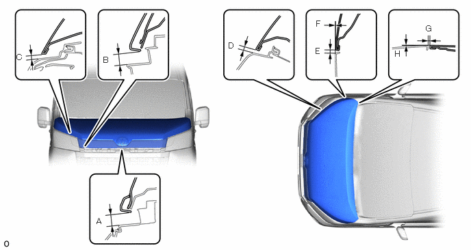
- Standard Clearance:
Area Measurement Area Measurement A 21.7 mm (0.854 in.) B 22.6 mm (0.890 in.) C 8.3 mm (0.327 in.) D 8.0 mm (0.315 in.) E 3.9 to 6.9 mm (0.154 to 0.272 in.) F -0.8 to 2.2 mm (-0.0315 to 0.0866 in.) G 2.3 to 5.3 mm (0.0906 to 0.2087 in.) H -1.5 to 1.5 mm (-0.0591 to 0.0591 in.)
- HINT:
-
Centering bolts are used to mount the hood hinge to the vehicle body and door. The door cannot be adjusted with the centering bolts on. Substitute the centering bolts for standard bolts when making adjustments.
ADJUST HOOD SUB-ASSEMBLY
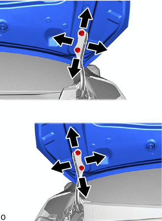
Adjust the hood position.
Loosen the 4 hinge bolts on the hood and adjust the hood position.
Move the hood and adjust the clearance between the hood and front fender.
Tighten the 4 hinge bolts on the hood after the adjustment.
- Torque:
- 11.5 N*m (117 kgf*cm, 8 ft.*lbf)
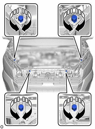
Adjust the 4 cushion rubbers so that the hood and fender are aligned.
- HINT:
-
Raise or lower the front end of the hood by turning the cushion rubber.

|
Protective Tape |
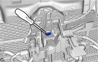
Adjust the hood lock.
Using a screwdriver with its tip wrapped in protective tape, remove the hood lock nut cap.
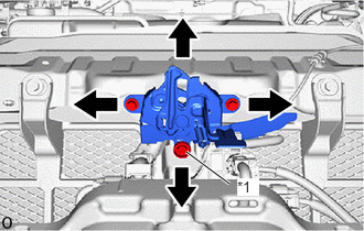
| *1 | Hood Lock Bolt |
Loosen the 2 bolts and hood lock bolt.
Adjust the hood lock position so that the striker can enter it smoothly.
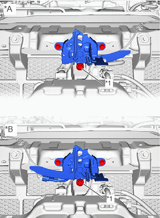
| *A | for LHD |
| *B | for RHD |
| *1 | Hood Lock Bolt |
Tighten the 2 bolts and hood lock bolt after the adjustment in the order shown in the illustration.
- Torque:
- 7.5 N*m (76 kgf*cm, 66 in.*lbf)
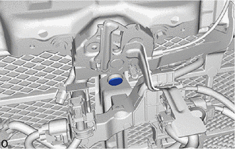
Install a new hood lock nut cap.
INSPECT FRONT DOOR PANEL SUB-ASSEMBLY LH
Check that the clearance measurements of areas A to N are within the standard ranges.
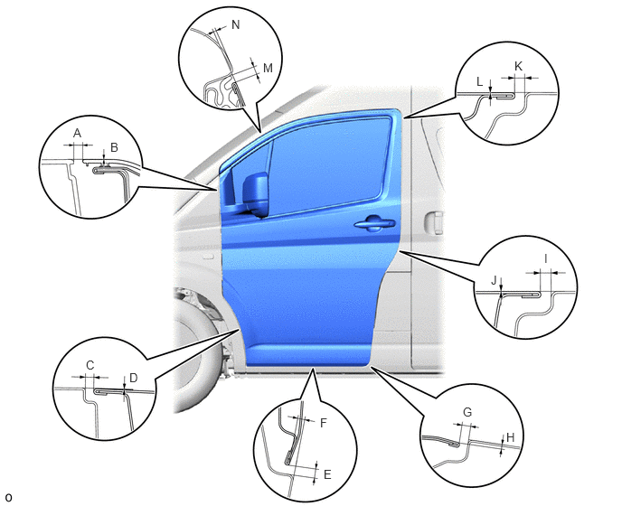
- Standard Clearance:
Area Measurement Area Measurement A 4.5 to 7.5 mm (0.177 to 0.295 in.) B -1.5 to 1.5 mm (-0.0591 to 0.0591 in.) C 3.2 to 6.2 mm (0.126 to 0.244 in.) D -1.4 to 1.6 mm (-0.0551 to 0.0630 in.) E 4.2 to 7.2 mm (0.165 to 0.283 in.) F -6.0 to -3.0 mm (-0.236 to -0.118 in.) G 3.6 to 6.6 mm (0.142 to 0.260 in.) H -4.4 to -1.4 mm (-0.1732 to -0.0551 in.) I 3.2 to 6.2 mm (0.126 to 0.244 in.) J -1.5 to 1.5 mm (-0.0591 to 0.0591 in.) K 3.2 to 6.2 mm (0.126 to 0.244 in.) L -1.5 to 1.5 mm (-0.0591 to 0.0591 in.) M 3.2 to 6.2 mm (0.126 to 0.244 in.) N 1.0 to 4.0 mm (0.0394 to 0.1575 in.)
- HINT:
- ·
Use the same procedure for RHD and LHD vehicles.
·The procedure listed below is for LHD vehicles.
·Use the same procedure for the RH and LH sides.
·Use the same procedure described for the LH side.
·Centering bolts are used to mount the door hinge to the vehicle body and door. The door cannot be adjusted with the centering bolts on. Substitute the centering bolts for standard bolts when making adjustments.
ADJUST FRONT DOOR PANEL SUB-ASSEMBLY LH
Remove the front pillar upper cover sub-assembly LH.
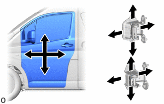
Using SST, loosen the hinge bolts on the body and adjust the door position.
- SST
- 09812-00010
Tighten the hinge bolts on the body after the adjustment.
- Torque:
- 26 N*m (265 kgf*cm, 19 ft.*lbf)
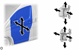
Loosen the hinge bolts on the door and adjust the door position.
Tighten the hinge bolts on the door after the adjustment.
- Torque:
- 21 N*m (214 kgf*cm, 15 ft.*lbf)
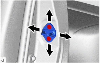
Using a T40 "TORX" socket wrench, adjust the striker position by slightly loosening the striker mounting screws and hitting the striker with a brass bar and a hammer.
Using a T40 "TORX" socket wrench, tighten the striker mounting screws after the adjustment.
- Torque:
- 23 N*m (235 kgf*cm, 17 ft.*lbf)
Install the front piller upper cover sub-assembly LH.
INSPECT SLIDE DOOR SUB-ASSEMBLY LH
for Standard Roof:
Check that the clearance measurements of areas A to N are within the standard ranges.
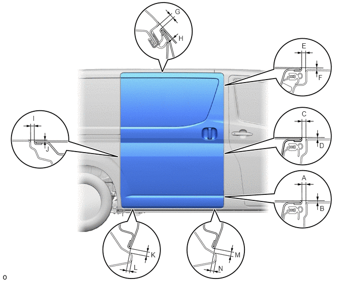
- Standard Clearance:
Area Measurement
(for Glass Type)
(except Glass Type)Area Measurement
(for Glass Type)
(except Glass Type)A 3.6 to 6.6 mm (0.142 to 0.260 in.)
3.6 to 6.6 mm (0.142 to 0.260 in.)B -1.5 to 1.5 mm (-0.0591 to 0.0591 in.)
-1.6 to 1.4 mm (-0.0630 to 0.0551 in.)C 3.6 to 6.6 mm (0.142 to 0.260 in.)
3.6 to 6.6 mm (0.142 to 0.260 in.)D -1.2 to 1.8 mm (-0.0472 to 0.0709 in.)
-1.4 to 1.6 mm (-0.0551 to 0.0630 in.)E 3.6 to 6.6 mm (0.142 to 0.260 in.)
3.6 to 6.6 mm (0.142 to 0.260 in.)F -1.4 to 1.6 mm (-0.0551 to 0.0630 in.)
-1.5 to 1.5 mm (-0.0591 to 0.0591 in.)G 4.4 to 7.4 mm (0.173 to 0.291 in.)
4.5 to 7.5 mm (0.177 to 0.295 in.)H -2.4 to 0.6 mm (-0.0945 to 0.0236 in.)
-2.2 to 0.8 mm (-0.0866 to 0.0315 in.)I 3.2 to 6.2 mm (0.126 to 0.244 in.)
3.2 to 6.2 mm (0.126 to 0.244 in.)J -1.5 to 1.5 mm (-0.0591 to 0.0591 in.)
-1.5 to 1.5 mm (-0.0591 to 0.0591 in.)K 5.0 to 8.0 mm (0.197 to 0.315 in.)
5.0 to 8.0 mm (0.197 to 0.315 in.)L -6.0 to -3.0 mm (-0.236 to -0.118 in.)
-6.2 to -3.2 mm (-0.244 to -0.126 in.)M 5.0 to 8.0 mm (0.197 to 0.315 in.)
5.0 to 8.0 mm (0.197 to 0.315 in.)N -5.9 to -2.9 mm (-0.232 to -0.114 in.)
-6.1 to -3.1 mm (-0.240 to -0.122 in.)
for High Roof:
Check that the clearance measurements of areas A to N are within the standard ranges.
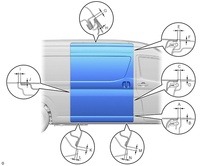
- Standard Clearance:
Area Measurement
(for Glass Type)
(except Glass Type)Area Measurement
(for Glass Type)
(except Glass Type)A 3.6 to 6.6 mm (0.142 to 0.260 in.)
3.6 to 6.6 mm (0.142 to 0.260 in.)B -1.4 to 1.6 mm (-0.0551 to 0.0630 in.)
-1.4 to 1.6 mm (-0.0551 to 0.0630 in.)C 3.6 to 6.6 mm (0.142 to 0.260 in.)
3.6 to 6.6 mm (0.142 to 0.260 in.)D -1.4 to 1.6 mm (-0.0551 to 0.0630 in.)
-1.4 to 1.6 mm (-0.0551 to 0.0630 in.)E 3.8 to 6.8 mm (0.150 to 0.268 in.)
3.8 to 6.8 mm (0.150 to 0.268 in.)F -1.5 to 1.5 mm (-0.0591 to 0.0591 in.)
-1.6 to 1.4 mm (-0.0630 to 0.0551 in.)G 4.6 to 7.6 mm (0.181 to 0.299 in.)
4.8 to 7.8 mm (0.189 to 0.307 in.)H -1.1 to 1.9 mm (-0.0433 to 0.0748 in.)
-0.7 to 2.3 mm (-0.0276 to 0.0906 in.)I 3.2 to 6.2 mm (0.126 to 0.244 in.)
3.2 to 6.2 mm (0.126 to 0.244 in.)J -1.5 to 1.5 mm (-0.0591 to 0.0591 in.)
-1.5 to 1.5 mm (-0.0591 to 0.0591 in.)K 4.9 to 7.9 mm (0.193 to 0.311 in.)
4.9 to 7.9 mm (0.193 to 0.311 in.)L -6.3 to -3.3 mm (-0.248 to -0.130 in.)
-6.3 to -3.3 mm (-0.248 to -0.130 in.)M 5.0 to 8.0 mm (0.197 to 0.315 in.)
5.0 to 8.0 mm (0.197 to 0.315 in.)N -5.9 to -2.9 mm (-0.232 to -0.114 in.)
-5.9 to -2.9 mm (-0.232 to -0.114 in.)
- HINT:
- ·
Use the same procedure for RHD and LHD vehicles.
·The procedure listed below is for LHD vehicles.
·Use the same procedure for the RH and LH sides.
·Use the same procedure described for the RH side.
ADJUST SLIDE DOOR SUB-ASSEMBLY LH
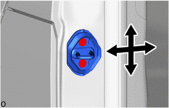
To adjust the door position vertically or horizontally at the slide door front lock striker plate assembly, loosen the bolts for the slide door down female stopper, loosen the striker screws using a T40 "TORX"socket wrench so that the striker can move, and then using a brass bar and hammer, adjust the striker position by tapping it lightly.
- Torque:
- 23 N*m (235 kgf*cm, 17 ft.*lbf)
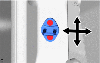
To adjust the door position vertically or horizontally at the slide door lock striker plate assembly, loosen the striker screws using a T40 "TORX" socket wrench, and then using a brass bar and hammer, adjust the position by tapping it lightly.
- Torque:
- 23 N*m (235 kgf*cm, 17 ft.*lbf)
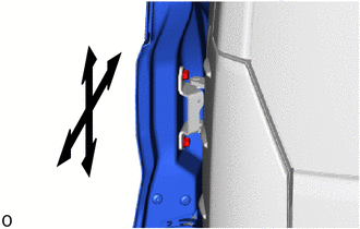
To adjust the door position in the vertical or front-to-back directions at the rear edge of the door, loosen the bolts of the center slide door hinge assembly LH before making an adjustment.
- Torque:
- 19.5 N*m (199 kgf*cm, 14 ft.*lbf)
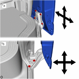
| *a | Door Side |
| *b | Vehicle Body Side |
To adjust the lower door seating position on the vehicle body surface vertically or to adjust the door position in the vertical and front-to-back directions, fully close the slide door, loosen the bolt of the lower slide door roller arm LH, and then check and adjust the door position.
- Torque:
- Door Side : 19.5 N*m (199 kgf*cm, 14 ft.*lbf)
- Vehicle Body Side : 19 N*m (194 kgf*cm, 14 ft.*lbf)
- HINT:
-
To adjust the slide door lower roller base on the vehicle body side, detach the slide door full open stop lock assembly and temporarily install the bolts.
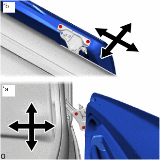
| *a | Door Side |
| *b | Vehicle Body Side |
To adjust the door position in the vertical, horizontal or front-to-back direction, loosen the bolts of the upper slide door roller assembly LH before making an adjustment.
- Torque:
- Door Side : 11.5 N*m (117 kgf*cm, 8 ft.*lbf)
- Vehicle Body Side : 30 N*m (306 kgf*cm, 22 ft.*lbf)
Temporarily tighten the slide door down female stopper, fully close the slide door to settle the stopper, and then fully tighten the stopper.
- Torque:
- 7.5 N*m (76 kgf*cm, 66 in.*lbf)
After adjusting the door position, check the operation of the electric door lock system, slide door closer system, and power slide door system (w/ Power Slide Door).
- HINT:
-
If something contacts the power slide door touch sensor during an automatic closing operation, the door will reverse.
INSPECT BACK DOOR PANEL SUB-ASSEMBLY
for Standard Roof:
Check that the clearance measurements of areas A to L are within the standard ranges.
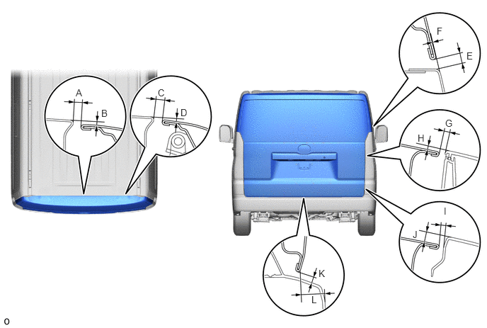
- Standard Clearance:
Area Measurement Area Measurement A 7.8 to 10.8 mm (0.307 to 0.425 in.) B 2.8 to 5.8 mm (0.110 to 0.228 in.) C 7.9 to 10.9 mm (0.311 to 0.429 in.) D 2.1 to 5.1 mm (0.0827 to 0.2008 in.) E 4.3 to 7.3 mm (0.169 to 0.287 in.) F -1.5 to 1.5 mm (-0.0591 to 0.0591 in.) G 3.5 to 7.5 mm (0.138 to 0.295 in.) H
(Reference)2.3 mm (0.0906 in.) I 3.5 to 7.5 mm (0.138 to 0.295 in.) J
(Reference)11.6 mm (0.457 in.) K 5.8 to 9.8 mm (0.228 to 0.386 in.) L
(Reference)26.7 mm (1.051 in.)
for High Roof:
Check that the clearance measurements of areas A to L are within the standard ranges.
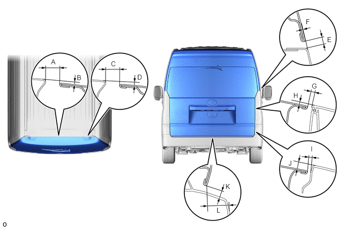
- Standard Clearance:
Area Measurement Area Measurement A 13.1 to 16.1 mm (0.516 to 0.634 in.) B 3.4 to 6.4 mm (0.134 to 0.252 in.) C 13.2 to 16.2 mm (0.520 to 0.638 in.) D 2.9 to 5.9 mm (0.114 to 0.232 in.) E 4.3 to 7.3 mm (0.169 to 0.287 in.) F -1.5 to 1.5 mm (-0.0591 to 0.0591 in.) G 3.5 to 7.5 mm (0.138 to 0.295 in.) H
(Reference)2.3 mm (0.0906 in.) I 3.5 to 7.5 mm (0.138 to 0.295 in.) J
(Reference)11.6 mm (0.457 in.) K
(Reference)8.0 mm (0.315 in.) L
(Reference)26.7 mm (1.051 in.)
- HINT:
-
Centering bolts are used to mount the door hinge to the vehicle body and door. The door cannot be adjusted with the centering bolts on. Substitute the centering bolts for standard bolts when making adjustments.
ADJUST BACK DOOR PANEL SUB-ASSEMBLY
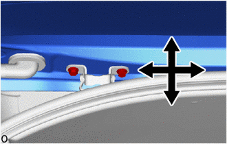
Before adjusting the upper end of the back door up and down or left and right, loosen the bolts.
Tighten the hinge bolts on the body after the adjustment.
- Torque:
- 19 N*m (194 kgf*cm, 14 ft.*lbf)
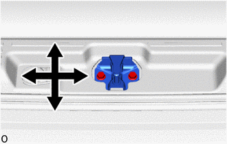
Adjust the striker position by slightly loosening the striker mounting bolts and hitting the striker with a brass bar and a hammer.
Tighten the striker mounting bolts after the adjustment.
- Torque:
- 19 N*m (194 kgf*cm, 14 ft.*lbf)
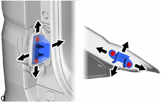
w/ Bracket:
After completing fitting adjustment, confirm the position of the back door side female stopper sub-assembly and back door side male stopper sub-assembly.
- Torque:
- 13 N*m (133 kgf*cm, 10 ft.*lbf)
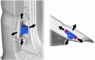
w/o Bracket:
After completing fitting adjustment, confirm the position of the back door No. 1 stopper and back door stopper cushion.
- Torque:
- 13 N*m (133 kgf*cm, 10 ft.*lbf)