BM35X0E
_01
Vehicle Exterior
_080418
BODY PANEL
_0390007
BACK DOOR OPENING SIDE REINFORCEMENT
F
BODY PANEL BACK DOOR OPENING SIDE REINFORCEMENT ASSEMBLY REPLACEMENT
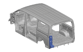
With the back door opening trough cut and join replacement sections removed.
REMOVAL
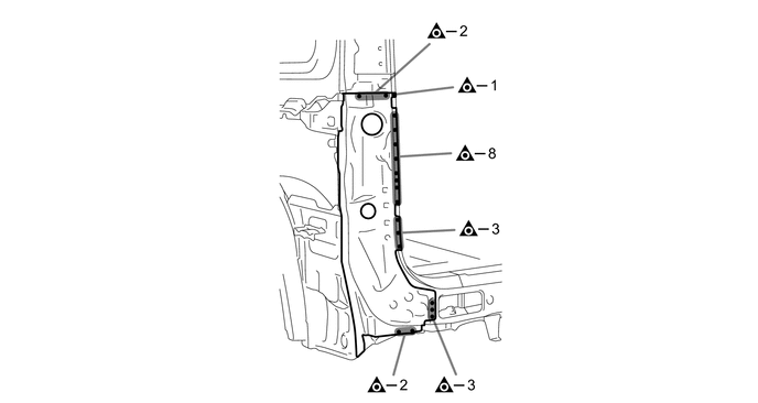
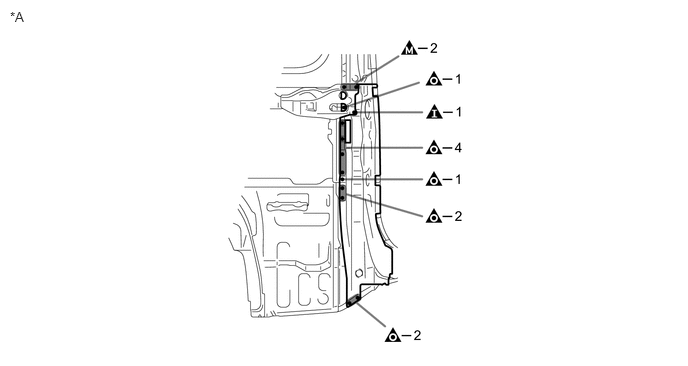
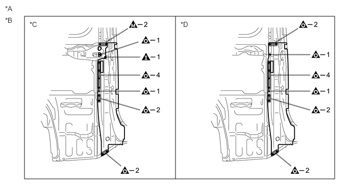
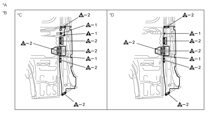
| Symbol Meaning | |
|---|---|

|
Remove Weld Points |

|
Remove Weld Points |

|
Remove Weld Points |
0.104,0.094 0.417,0.25
0.313,0.156
10
false
*A
| *A | for 5 Door | - | - |
0.5,0.333 6.833,3.667
6.333,3.333
3.583,3.667 3.583,0.333
false
0.104,0.094 0.417,0.25
0.313,0.156
10
false
*A
0.104,0.333 0.417,0.49
0.313,0.156
10
false
*B
0.604,0.417 0.917,0.573
0.313,0.156
10
false
*C
3.688,0.417 4,0.573
0.313,0.156
10
false
*D
| *A | for 4 Door | *B | for Type A |
| *C | for Passenger Side | *D | for Driver Side |
0.5,0.333 6.833,3.667
6.333,3.333
3.583,3.667 3.583,0.333
false
0.083,0.083 0.396,0.24
0.313,0.156
10
false
*A
0.083,0.344 0.396,0.5
0.313,0.156
10
false
*B
0.583,0.417 0.896,0.573
0.313,0.156
10
false
*C
3.667,0.417 3.979,0.573
0.313,0.156
10
false
*D
| *A | for 4 Door | *B | for Type B |
| *C | for Passenger Side | *D | for Driver Side |
INSTALLATION
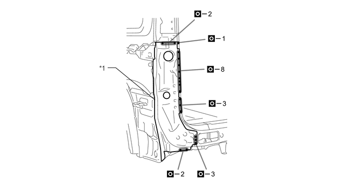
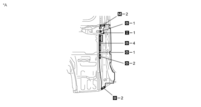
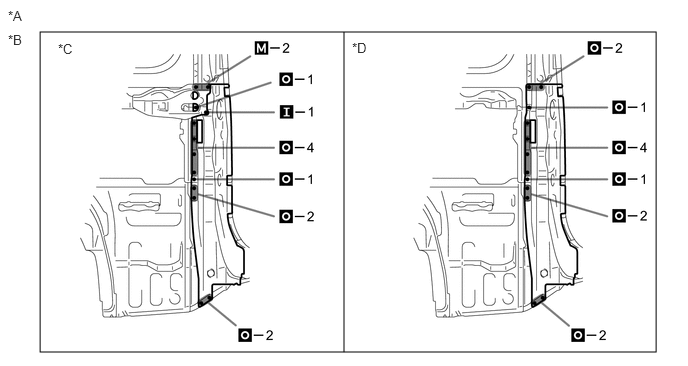
| Symbol Meaning | |
|---|---|

|
Plug Weld |

|
Plug Weld |

|
Plug Weld |
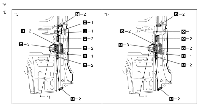
a.
Inspect the fitting of the related parts around the new parts before welding. This affects the appearance of the finish.
b.
Temporarily install the new parts and measure each part of the new parts in accordance with the body dimension diagram. (See the body dimensions)
2.25,1.417 2.417,1.417
2.417,1.417 3.24,2.094
false
2.073,1.344 2.385,1.5
0.313,0.156
10
false
*1
| *1 | BACK DOOR OPENING REINFORCEMENT LOWER | - | - |
0.104,0.094 0.417,0.25
0.313,0.156
10
false
*A
| *A | for 5 Door | - | - |
0.417,0.333 6.833,3.667
6.417,3.333
3.583,3.667 3.583,0.333
false
0.083,0.083 0.396,0.24
0.313,0.156
10
false
*A
0.083,0.333 0.396,0.49
0.313,0.156
10
false
*B
3.667,0.417 3.979,0.573
0.313,0.156
10
false
*D
0.604,0.427 0.917,0.583
0.313,0.156
10
false
*C
| *A | for 4 Door | *B | for Type A |
| *C | for Passenger Side | *D | for Driver Side |
0.417,0.333 6.917,3.667
6.5,3.333
3.583,3.667 3.583,0.333
false
1.583,3.417 1.417,3.417
1.417,3.417 1.781,1.792
false
5.052,3.417 4.885,3.417
4.885,3.417 5.25,1.792
false
0.083,0.083 0.396,0.24
0.313,0.156
10
false
*A
0.083,0.344 0.396,0.5
0.313,0.156
10
false
*B
3.667,0.427 3.979,0.583
0.313,0.156
10
false
*D
1.646,3.344 1.958,3.5
0.313,0.156
10
false
*1
5.104,3.333 5.417,3.49
0.313,0.156
10
false
*1
0.5,0.417 0.813,0.573
0.313,0.156
10
false
*C
| *A | for 4 Door | *B | for Type B |
| *C | for Passenger Side | *D | for Driver Side |
| *1 | REAR SEAT REINFORCEMENT SUB-ASSEMBLY NO.5 | - | - |
c.
After welding, apply the foamed sealing material to the corresponding parts. (See the painting/coating)
d.
After applying the top coat, apply anti-rust agent to the internal panel portion of the closed section structural weld points.