Home › Vehicle Exterior › BODY PANEL › REAR FLOOR PAN (for Van)
BM35X0E _01 Vehicle Exterior _080418 BODY PANEL _0390011 REAR FLOOR PAN(for Van) F

BODY PANEL  REAR FLOOR PAN(for Van)  CUT AND JOIN REPLACEMENT SECTIONS  

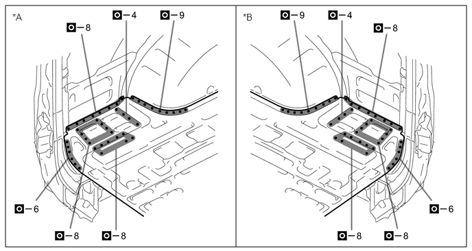
K151925

With the rear floor rear inner crossmember cut and join replacement sections (small areas) removed.


REMOVAL


Symbol Meaning
K108818

Remove Weld Points
K108827

Cut and Join Location
K108829

Cut Location

a.

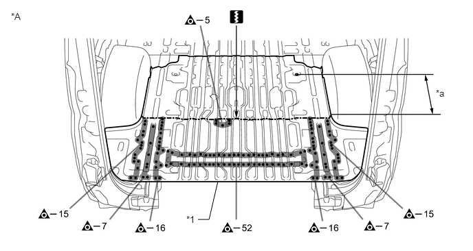
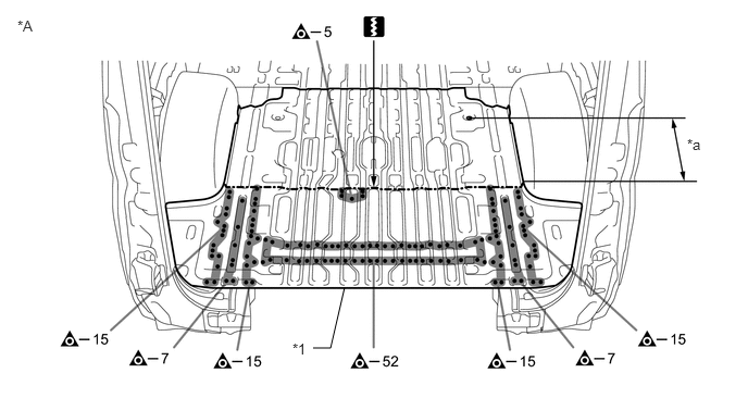
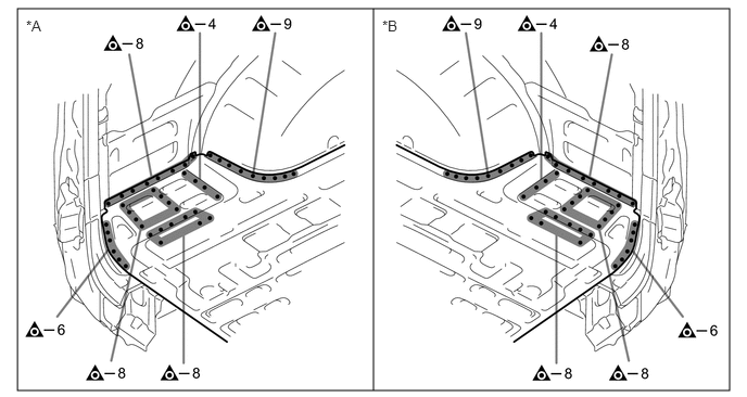
Remove the rear floor panel rear.

K151037C01
3,3.333 3.167,3.333 3.167,3.333 3.302,2.75 false 0.167,0.167 0.479,0.323 0.313,0.156 10 false *A 6.604,1.333 6.917,1.49 0.313,0.156 10 false *a 2.823,3.25 3.135,3.406 0.313,0.156 10 false *1
*A for Standard Roof - -
*1 REAR FLOOR PANEL REAR - -
*a 570 mm (22.44 in.) - -


K151038C01
3,3.333 3.167,3.333 3.167,3.333 3.302,2.75 false 0.167,0.167 0.479,0.323 0.313,0.156 10 false *A 6.583,1.302 6.896,1.458 0.313,0.156 10 false *a 2.802,3.26 3.115,3.417 0.313,0.156 10 false *1
*A for High Roof - -
*1 REAR FLOOR PANEL REAR - -
*a 570 mm (22.44 in.) - -


K151039C01
0.167,0.083 7,3.75 6.833,3.667 3.583,3.75 3.583,0.083 false 0.25,0.167 0.563,0.323 0.313,0.156 10 false *A 3.667,0.167 3.979,0.323 0.313,0.156 10 false *B
*A LH Side *B RH Side


b.

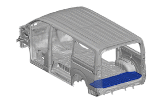
Remove the front side member plate No.7 and floor plate rear to the vehicle side.
K151040C01
0.083,0.083 7.083,3.667 7,3.583 3.583,3.667 3.583,0.083 false 1.333,3.417 1.5,3.417 1.5,3.417 1.302,2.823 false 5.833,3.417 5.667,3.417 5.667,3.417 5.823,2.813 false 5.615,2.021 5.667,0.25 5.667,0.25 5.833,0.25 false 1.563,2.031 1.5,0.25 1.5,0.25 1.333,0.25 false 0.188,0.177 0.5,0.333 0.313,0.156 10 false *A 3.688,0.177 4,0.333 0.313,0.156 10 false *B 3.313,2.271 3.625,2.427 0.313,0.156 10 false *a 3.719,2.271 4.031,2.427 0.313,0.156 10 false *a 1.156,3.354 1.469,3.51 0.313,0.156 10 false *1 1.167,0.177 1.479,0.333 0.313,0.156 10 false *2 5.885,3.354 6.198,3.51 0.313,0.156 10 false *1 5.885,0.188 6.198,0.344 0.313,0.156 10 false *2
*A LH Side *B RH Side
*1 FRONT SIDE MEMBER PLATE NO.7 *2 FLOOR PLATE REAR
*a 50 mm (1.97 in.) - -


INSTALLATION


Symbol Meaning
K108823

Plug Weld
K108827

Cut and Join Location
K108829

Cut Location
K108831

Butt Weld
K108834

Body Sealer

a.

Cut the new part so that it overlaps the previous cut location by approximately 30 mm (1.18 in.).
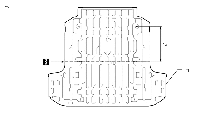
K151041C01
5.521,2.833 5.917,2.333 5.917,2.333 6.083,2.333 false 0.167,0.167 0.479,0.323 0.313,0.156 10 false *A 6.188,2.26 6.5,2.417 0.313,0.156 10 false *1 5.427,1.396 5.74,1.552 0.313,0.156 10 false *a
*A Upper Face - -
*1 REAR FLOOR PANEL REAR - -
*a 540 mm (21.26 in.) - -


b.

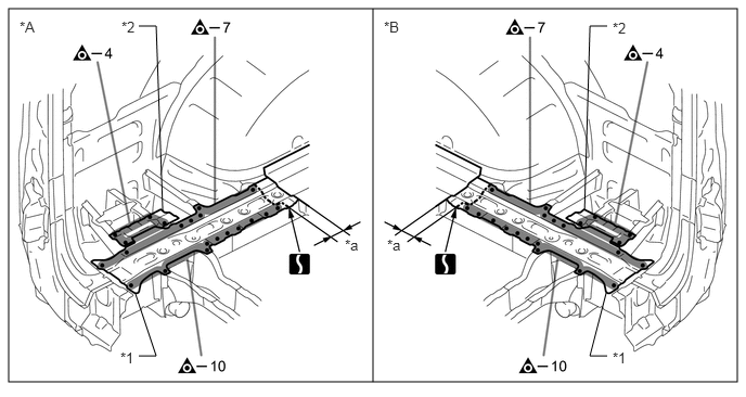
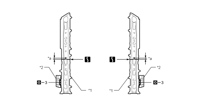
Before temporarily installing the new parts, weld the front side member plate No.7 and floor plate rear with the standard number of welding points.
K151042C01
2.563,2.781 2.917,3.25 2.917,3.25 3.083,3.25 false 5.146,2.792 5.417,2.417 5.417,2.417 5.583,2.417 false 4.083,3.25 4.25,3.25 4.25,3.25 4.594,2.792 false 2.01,2.833 1.75,2.417 1.75,2.417 1.583,2.417 false 3.167,3.167 3.479,3.323 0.313,0.156 10 false *1 1.417,2.344 1.729,2.5 0.313,0.156 10 false *2 1.708,2.01 2.021,2.167 0.313,0.156 10 false *a 5.313,2.021 5.625,2.177 0.313,0.156 10 false *a 5.625,2.344 5.938,2.5 0.313,0.156 10 false *2 3.917,3.177 4.229,3.333 0.313,0.156 10 false *1
*1 FRONT SIDE MEMBER PLATE NO.7 *2 FLOOR PLATE REAR
*a 20 mm (0.79 in.)


c.

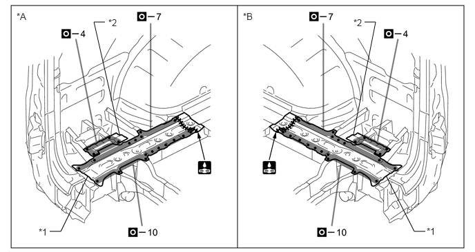
Weld the front side member plate No.7 and floor plate rear to the vehicle side.
K151043C01
0.167,0.083 7,3.75 6.833,3.667 3.583,3.75 3.583,0.083 false 0.75,3.5 0.917,3.5 0.917,3.5 1.323,2.667 false 1.802,2.031 1.417,0.333 1.417,0.333 1.583,0.333 false 6.417,3.5 6.25,3.5 6.25,3.5 5.823,2.656 false 5.333,2.031 5.667,0.333 5.667,0.333 5.5,0.333 false 0.25,0.167 0.563,0.323 0.313,0.156 10 false *A 3.667,0.167 3.979,0.323 0.313,0.156 10 false *B 0.583,3.427 0.896,3.583 0.313,0.156 10 false *1 6.438,3.417 6.75,3.573 0.313,0.156 10 false *1 5.333,0.26 5.646,0.417 0.313,0.156 10 false *2 1.635,0.26 1.948,0.417 0.313,0.156 10 false *2
*A LH Side *B RH Side
*1 FRONT SIDE MEMBER PLATE NO.7 *2 FLOOR PLATE REAR


d.

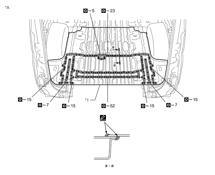
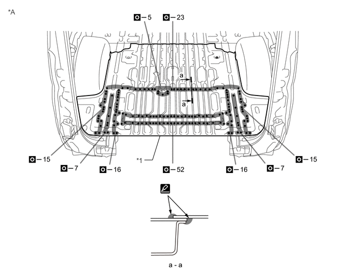
Weld the rear floor panel rear to the vehicle side.

i.

Perform plug-welding in the area where the panel are overlapped. Apply body sealer to each panel.

HINT:
·

Confirm that the panels are securely welded together.

·

Apply body sealer in an even, continuous bead.


K151045C01
3,3.333 3.167,3.333 3.167,3.333 3.323,2.833 false 0.167,0.167 0.479,0.323 0.313,0.156 10 false *A 2.833,3.26 3.146,3.417 0.313,0.156 10 false *1
*A for Standard Roof - -
*1 REAR FLOOR PANEL REAR - -


K151046C01
3,3.333 3.167,3.333 3.167,3.333 3.333,2.813 false 0.167,0.167 0.479,0.365 0.313,0.198 10 false *A 2.833,3.25 3.146,3.448 0.313,0.198 10 false *1
*A for High Roof - -
*1 REAR FLOOR PANEL REAR - -


K151044C01
0.083,0.083 7.083,3.75 7,3.667 3.583,3.75 3.583,0.083 false 0.188,0.177 0.5,0.333 0.313,0.156 10 false *A 3.688,0.177 4,0.333 0.313,0.156 10 false *B
*A LH Side *B RH Side


e.

After applying the top coat, apply anti-rust agent to the internal panel portion of the closed section structural weld points.


f.

After welding, apply body sealer and undercoating to the corresponding parts. (See the painting/coating)