BODY PANEL REAR FLOOR PAN(for Wagon) CUT AND JOIN REPLACEMENT SECTIONS
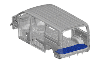
With the rear floor rear inner crossmember cut and join replacement sections (small areas) removed.
REMOVAL
| Symbol Meaning | |
|---|---|

|
Remove Weld Points |

|
Cut and Join Location |

|
Cut Location |
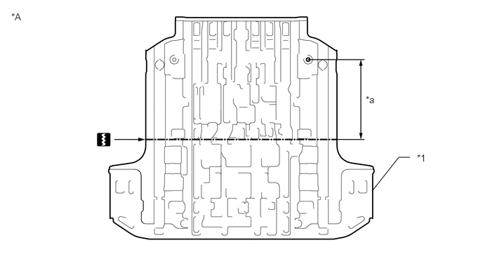
Remove the rear floor panel rear.
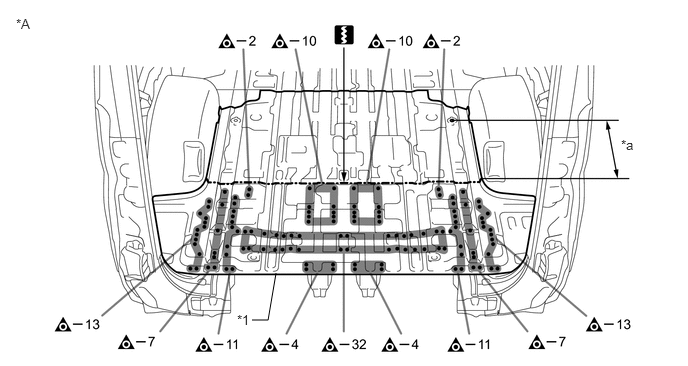
| *A | for Space Up Seat | - | - |
| *1 | REAR FLOOR PANEL REAR | - | - |
| *a | 575 mm (22.64 in.) | - | - |
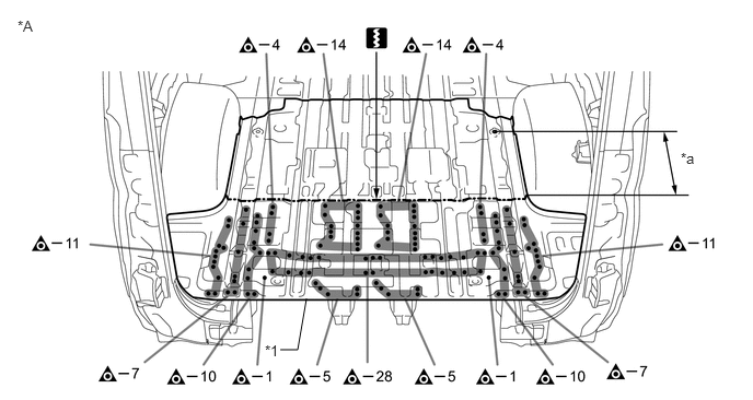
| *A | for Tip Up Seat | - | - |
| *1 | REAR FLOOR PANEL REAR | - | - |
| *a | 575 mm (22.64 in.) | - | - |
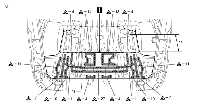
| *A | for 6-Passenger | - | - |
| *1 | REAR FLOOR PANEL REAR | - | - |
| *a | 575 mm (22.64 in.) | - | - |
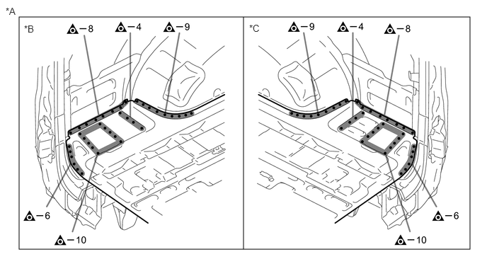
| *A | for Space Up Seat | *B | LH Side |
| *C | RH Side | - | - |
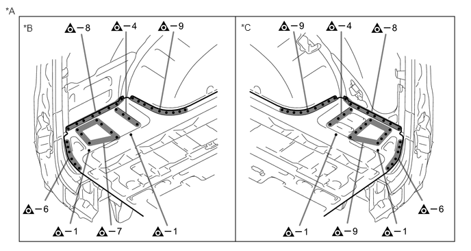
| *A | except Space Up Seat | *B | LH Side |
| *C | RH Side | - | - |
Remove the front side member plate No.7 and floor plate rear to the vehicle side.
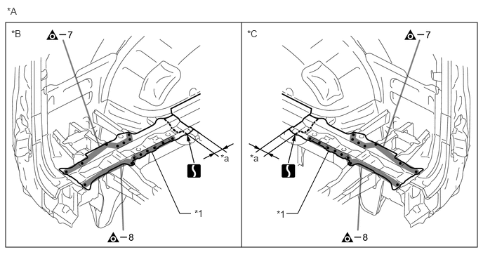
| *A | for Space Up Seat | *B | LH Side |
| *C | RH Side | - | - |
| *1 | FRONT SIDE MEMBER PLATE NO.7 | - | - |
| *a | 50 mm (1.97 in.) | - | - |
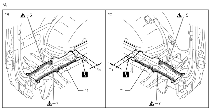
| *A | except Space Up Seat | *B | LH Side |
| *C | RH Side | - | - |
| *1 | FRONT SIDE MEMBER PLATE NO.7 | - | - |
| *a | 50 mm (1.97 in.) | - | - |
INSTALLATION
| Symbol Meaning | |
|---|---|

|
Plug Weld |
|
|
Cut and Join Location |
|
|
Cut Location |

|
Butt Weld |

|
Body Sealer |
Cut the new part so that it overlaps the previous cut location by approximately 30 mm (1.18 in.).
| *A | Upper Face | - | - |
| *1 | REAR FLOOR PANEL REAR | - | - |
| *a | 545 mm (21.46 in.) | - | - |
Before temporarily installing the new parts, weld the rear floor panel rear, oscillator electrical key bracket and cable clamp bracket No.2 with the standard number of welding points.
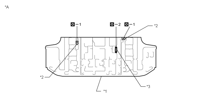
| *A | Upper Face | - | - |
| *1 | REAR FLOOR PANEL REAR | *2 | OSCILLATOR ELECTRICAL KEY BRACKET |
| *3 | CABLE CLAMP BRACKET NO.2 | - | - |
Before temporarily installing the new parts, weld the rear floor panel rear, oscillator electrical key bracket, cable clamp bracket No.2 and extinguisher bracket No.1 with the standard number of welding points.
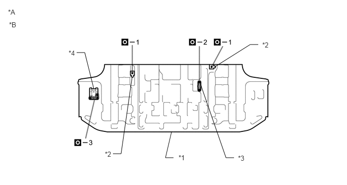
| *A | Upper Face | *B | w/ Extinguisher Bracket No.1 |
| *1 | REAR FLOOR PANEL REAR | *2 | OSCILLATOR ELECTRICAL KEY BRACKET |
| *3 | CABLE CLAMP BRACKET NO.2 | *4 | EXTINGUISHER BRACKET NO.1 |
Weld the front side member plate No.7 to the vehicle side.
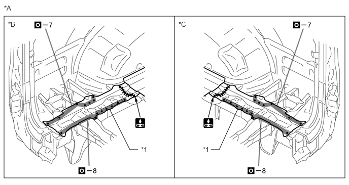
| *A | for Space Up Seat | *B | LH Side |
| *C | RH Side | - | - |
| *1 | FRONT SIDE MEMBER PLATE NO.7 | - | - |
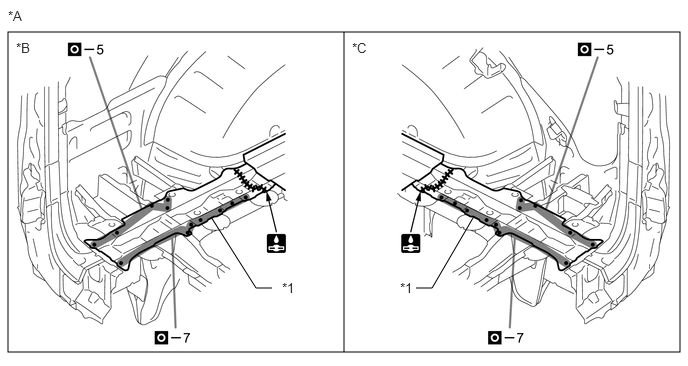
| *A | except Space Up Seat | *B | LH Side |
| *C | RH Side | - | - |
| *1 | FRONT SIDE MEMBER PLATE NO.7 | - | - |
Weld the rear floor panel rear to the vehicle side.
Perform plug-welding in the area where the panel are overlapped. Apply body sealer to each panel.
- HINT:
- ·
Confirm that the panels are securely welded together.
·Apply body sealer in an even, continuous bead.
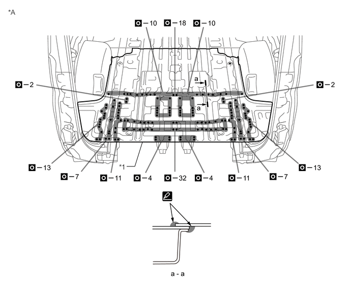
| *A | for Space Up Seat | - | - |
| *1 | REAR FLOOR PANEL REAR | - | - |
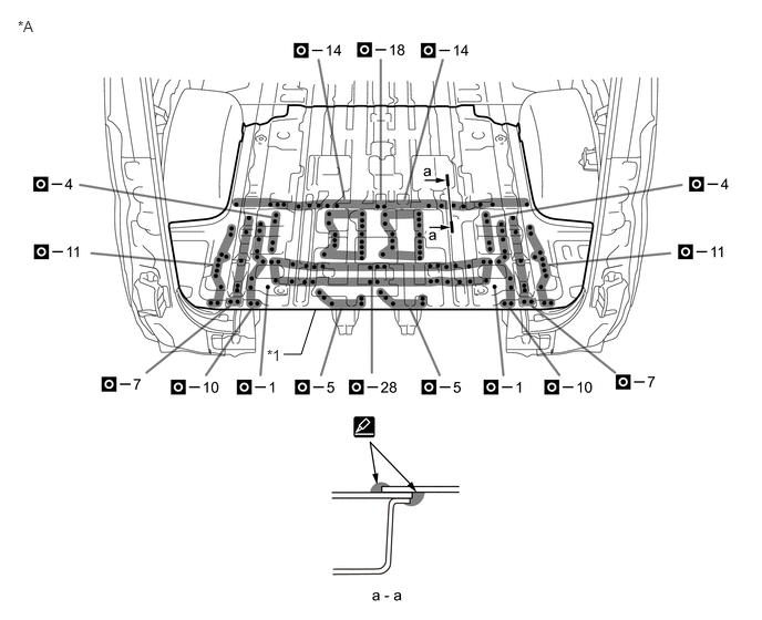
| *A | for Tip Up Seat | - | - |
| *1 | REAR FLOOR PANEL REAR | - | - |
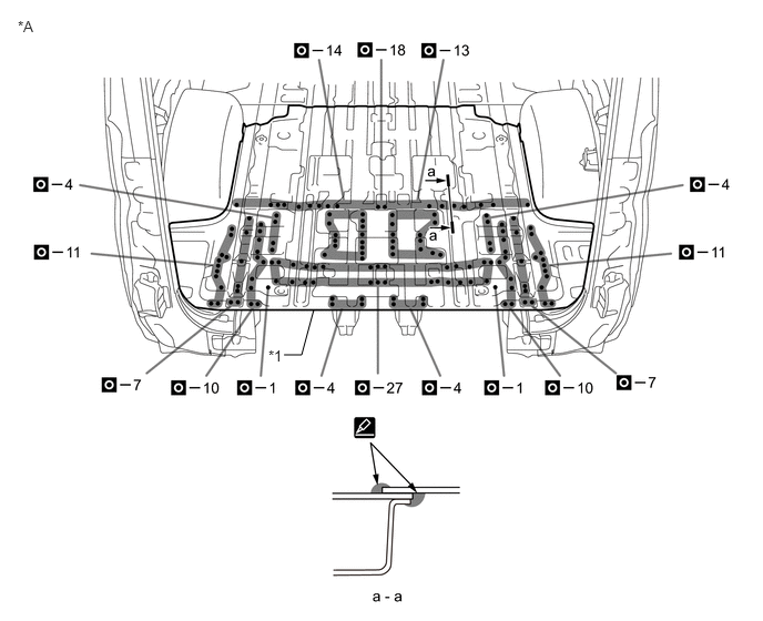
| *A | for 6-Passenger | - | - |
| *1 | REAR FLOOR PANEL REAR | - | - |
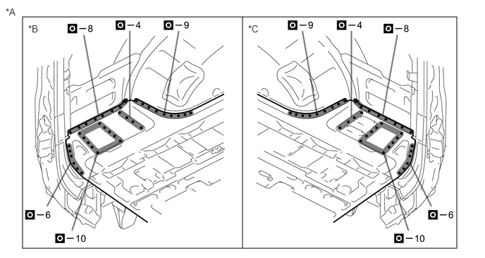
| *A | for Space Up Seat | *B | LH Side |
| *C | RH Side | - | - |
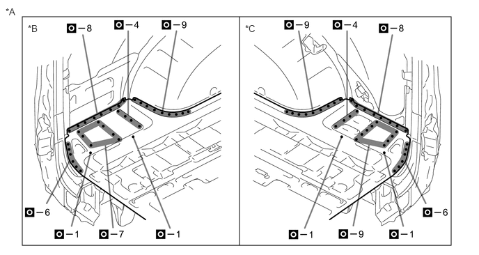
| *A | except Space Up Seat | *B | LH Side |
| *C | RH Side | - | - |
After applying the top coat, apply anti-rust agent to the internal panel portion of the closed section structural weld points.
After welding, apply body sealer and undercoating to the corresponding parts. (See the painting/coating)