BODY PANEL FIT STANDARD / ADJUSTMENT METHOD ADJUSTMENT
Refer to the TOYOTA Repair Manual for adjustment method.
- HINT:
-
Vehicle Exterior > DOOR / HATCH
INSPECT HOOD SUB-ASSEMBLY
Check that the clearance measurements of areas A to H are within the standard ranges.
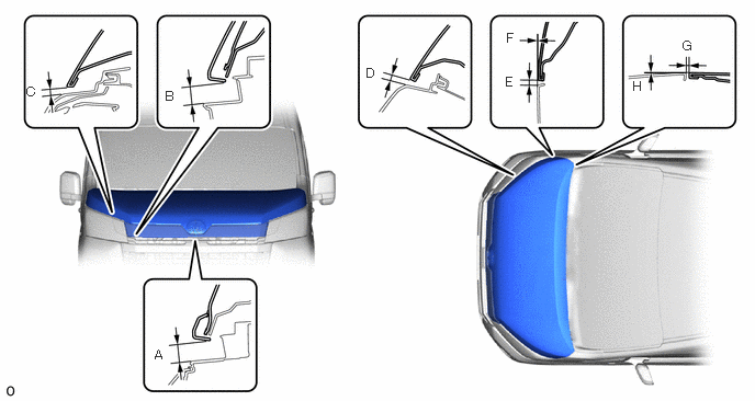
- Standard Clearance:
Area Measurement Area Measurement A 21.7 mm (0.854 in.) B 22.6 mm (0.890 in.) C 8.3 mm (0.327 in.) D 8.0 mm (0.315 in.) E 3.9 to 6.9 mm (0.154 to 0.272 in.) F -0.8 to 2.2 mm (-0.0315 to 0.0866 in.) G 2.3 to 5.3 mm (0.0906 to 0.2087 in.) H -1.5 to 1.5 mm (-0.0591 to 0.0591 in.)
- HINT:
-
Centering bolts are used to mount the hood hinge to the vehicle body and hood. The hood cannot be adjusted with the centering bolts on. Substitute the centering bolts for standard bolts (with washers) when making adjustments.
INSPECT FRONT DOOR PANEL SUB-ASSEMBLY LH
Check that the clearance measurements of areas A to N are within the standard ranges.
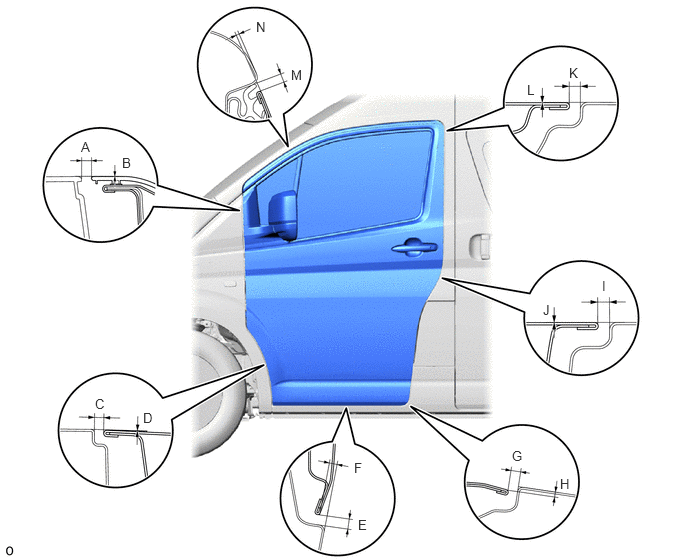
- Standard Clearance:
Area Measurement Area Measurement A 4.5 to 7.5 mm (0.177 to 0.295 in.) B -1.5 to 1.5 mm (-0.0591 to 0.0591 in.) C 3.2 to 6.2 mm (0.126 to 0.244 in.) D -1.4 to 1.6 mm (-0.0551 to 0.0630 in.) E 4.2 to 7.2 mm (0.165 to 0.283 in.) F -6.0 to -3.0 mm (-0.236 to -0.118 in.) G 3.6 to 6.6 mm (0.142 to 0.260 in.) H -4.4 to -1.4 mm (-0.1732 to -0.0551 in.) I 3.2 to 6.2 mm (0.126 to 0.244 in.) J -1.5 to 1.5 mm (-0.0591 to 0.0591 in.) K 3.2 to 6.2 mm (0.126 to 0.244 in.) L -1.5 to 1.5 mm (-0.0591 to 0.0591 in.) M 3.2 to 6.2 mm (0.126 to 0.244 in.) N 1.0 to 4.0 mm (0.0394 to 0.1575 in.)
- HINT:
- ·
Use the same procedure for RHD and LHD vehicles.
·The procedure listed below is for LHD vehicles.
·Use the same procedure for the RH and LH sides.
·Use the same procedure described for the LH side.
·Centering bolts are used to mount the door hinge to the vehicle body and door. The door cannot be adjusted with the centering bolts on. Substitute the centering bolts for standard bolts when making adjustments.
INSPECT SLIDE DOOR SUB-ASSEMBLY LH (for Wagon)
Check that the clearance measurements of areas A to N are within the standard ranges.
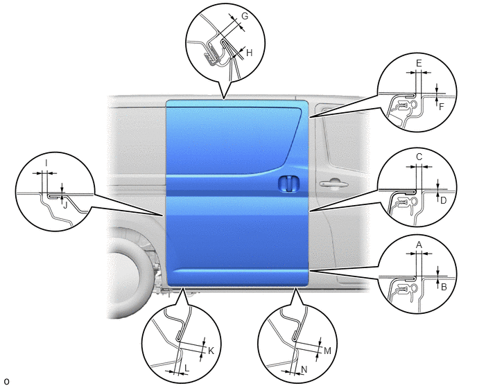
- Standard Clearance:
Area Measurement
(for Glass Type)
(except Glass Type)Area Measurement A 3.6 to 6.6 mm (0.142 to 0.260 in.)
3.6 to 6.6 mm (0.142 to 0.260 in.)B -1.5 to 1.5 mm (-0.0591 to 0.0591 in.) C 3.6 to 6.6 mm (0.142 to 0.260 in.)
3.6 to 6.6 mm (0.142 to 0.260 in.)D -1.5 to 1.5 mm (-0.0591 to 0.0591 in.) E 3.6 to 6.6 mm (0.142 to 0.260 in.)
3.6 to 6.6 mm (0.142 to 0.260 in.)F -1.5 to 1.5 mm (-0.0591 to 0.0591 in.) G 4.4 to 7.4 mm (0.173 to 0.291 in.)
4.5 to 7.5 mm (0.177 to 0.295 in.)H -2.4 to 0.6 mm (-0.0945 to 0.0236 in.) I 3.2 to 6.2 mm (0.126 to 0.244 in.)
3.2 to 6.2 mm (0.126 to 0.244 in.)J -1.5 to 1.5 mm (-0.0591 to 0.0591 in.) K 5.0 to 8.0 mm (0.197 to 0.315 in.)
5.0 to 8.0 mm (0.197 to 0.315 in.)L -5.9 to -2.9 mm (-0.232 to -0.114 in.) M 5.0 to 8.0 mm (0.197 to 0.315 in.)
5.0 to 8.0 mm (0.197 to 0.315 in.)N -5.9 to -2.9 mm (-0.232 to -0.114 in.)
- HINT:
- ·
Use the same procedure for RHD and LHD vehicles.
·The procedure listed below is for LHD vehicles.
·Use the same procedure for the RH and LH sides.
·Use the same procedure described for the RH side.
INSPECT SLIDE DOOR SUB-ASSEMBLY LH (except Wagon)
for Standard Roof:
Check that the clearance measurements of areas A to N are within the standard ranges.
- Standard Clearance:
Area Measurement
(for Glass Type)
(except Glass Type)Area Measurement
(for Glass Type)
(except Glass Type)A 3.6 to 6.6 mm (0.142 to 0.260 in.)
3.6 to 6.6 mm (0.142 to 0.260 in.)B -1.5 to 1.5 mm (-0.0591 to 0.0591 in.)
-1.6 to 1.4 mm (-0.0630 to 0.0551 in.)C 3.6 to 6.6 mm (0.142 to 0.260 in.)
3.6 to 6.6 mm (0.142 to 0.260 in.)D -1.2 to 1.8 mm (-0.0472 to 0.0709 in.)
-1.4 to 1.6 mm (-0.0551 to 0.0630 in.)E 3.6 to 6.6 mm (0.142 to 0.260 in.)
3.6 to 6.6 mm (0.142 to 0.260 in.)F -1.4 to 1.6 mm (-0.0551 to 0.0630 in.)
-1.5 to 1.5 mm (-0.0591 to 0.0591 in.)G 4.4 to 7.4 mm (0.173 to 0.291 in.)
4.5 to 7.5 mm (0.177 to 0.295 in.)H -2.4 to 0.6 mm (-0.0945 to 0.0236 in.)
-2.2 to 0.8 mm (-0.0866 to 0.0315 in.)I 3.2 to 6.2 mm (0.126 to 0.244 in.)
3.2 to 6.2 mm (0.126 to 0.244 in.)J -1.5 to 1.5 mm (-0.0591 to 0.0591 in.)
-1.5 to 1.5 mm (-0.0591 to 0.0591 in.)K 5.0 to 8.0 mm (0.197 to 0.315 in.)
5.0 to 8.0 mm (0.197 to 0.315 in.)L -6.0 to -3.0 mm (-0.236 to -0.118 in.)
-6.2 to -3.2 mm (-0.244 to -0.126 in.)M 5.0 to 8.0 mm (0.197 to 0.315 in.)
5.0 to 8.0 mm (0.197 to 0.315 in.)N -5.9 to -2.9 mm (-0.232 to -0.114 in.)
-6.1 to -3.1 mm (-0.240 to -0.122 in.)
for High Roof:
Check that the clearance measurements of areas A to N are within the standard ranges.
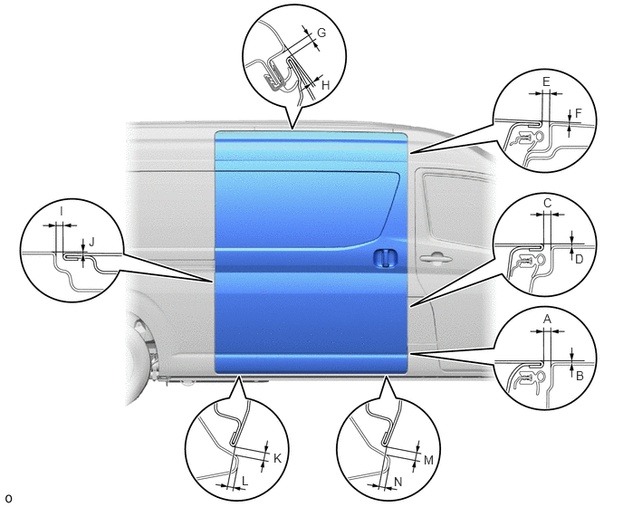
- Standard Clearance:
Area Measurement
(for Glass Type)
(except Glass Type)Area Measurement
(for Glass Type)
(except Glass Type)A 3.6 to 6.6 mm (0.142 to 0.260 in.)
3.6 to 6.6 mm (0.142 to 0.260 in.)B -1.4 to 1.6 mm (-0.0551 to 0.0630 in.)
-1.4 to 1.6 mm (-0.0551 to 0.0630 in.)C 3.6 to 6.6 mm (0.142 to 0.260 in.)
3.6 to 6.6 mm (0.142 to 0.260 in.)D -1.4 to 1.6 mm (-0.0551 to 0.0630 in.)
-1.4 to 1.6 mm (-0.0551 to 0.0630 in.)E 3.8 to 6.8 mm (0.150 to 0.268 in.)
3.8 to 6.8 mm (0.150 to 0.268 in.)F -1.5 to 1.5 mm (-0.0591 to 0.0591 in.)
-1.6 to 1.4 mm (-0.0630 to 0.0551 in.)G 4.6 to 7.6 mm (0.181 to 0.299 in.)
4.8 to 7.8 mm (0.189 to 0.307 in.)H -1.1 to 1.9 mm (-0.0433 to 0.0748 in.)
-0.7 to 2.3 mm (-0.0276 to 0.0906 in.)I 3.2 to 6.2 mm (0.126 to 0.244 in.)
3.2 to 6.2 mm (0.126 to 0.244 in.)J -1.5 to 1.5 mm (-0.0591 to 0.0591 in.)
-1.5 to 1.5 mm (-0.0591 to 0.0591 in.)K 4.9 to 7.9 mm (0.193 to 0.311 in.)
4.9 to 7.9 mm (0.193 to 0.311 in.)L -6.3 to -3.3 mm (-0.248 to -0.130 in.)
-6.3 to -3.3 mm (-0.248 to -0.130 in.)M 5.0 to 8.0 mm (0.197 to 0.315 in.)
5.0 to 8.0 mm (0.197 to 0.315 in.)N -5.9 to -2.9 mm (-0.232 to -0.114 in.)
-5.9 to -2.9 mm (-0.232 to -0.114 in.)
- HINT:
- ·
Use the same procedure for RHD and LHD vehicles.
·The procedure listed below is for LHD vehicles.
·Use the same procedure for the RH and LH sides.
·Use the same procedure described for the RH side.
INSPECT BACK DOOR PANEL SUB-ASSEMBLY (for Wagon)
Check that the clearance measurements of areas A to L are within the standard ranges.
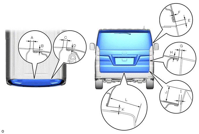
- Standard Clearance:
Area Measurement Area Measurement A 7.7 to 10.7 mm (0.303 to 0.421 in.) B 2.1 to 5.1 mm (0.0827 to 0.2008 in.) C 7.7 to 10.7 mm (0.303 to 0.421 in.) D 1.6 to 4.6 mm (0.0630 to 0.1811 in.) E 4.0 to 7.0 mm (0.157 to 0.276 in.) F -1.5 to 1.5 mm (-0.0591 to 0.0591 in.) G 3.15 to 7.15 mm (0.124 to 0.281 in.) H 2.5 mm (0.0984 in.) I 3.15 to 7.15 mm (0.124 to 0.281 in.) J 36.6 mm (1.44 in.) K 5.85 to 9.85 mm (0.230 to 0.388 in.) L 49.9 mm (1.96 in.)
- HINT:
-
Centering bolts are used to mount the door hinge to the vehicle body and door. The door cannot be adjusted with the centering bolts on. Substitute the centering bolts for standard bolts when making adjustments.
INSPECT BACK DOOR PANEL SUB-ASSEMBLY (except Wagon)
for Standard Roof:
Check that the clearance measurements of areas A to L are within the standard ranges.
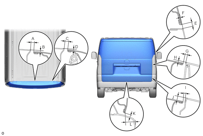
- Standard Clearance:
Area Measurement Area Measurement A 7.8 to 10.8 mm (0.307 to 0.425 in.) B 2.8 to 5.8 mm (0.110 to 0.228 in.) C 7.9 to 10.9 mm (0.311 to 0.429 in.) D 2.1 to 5.1 mm (0.0827 to 0.2008 in.) E 4.3 to 7.3 mm (0.169 to 0.287 in.) F -1.5 to 1.5 mm (-0.0591 to 0.0591 in.) G 3.5 to 7.5 mm (0.138 to 0.295 in.) H
(Reference)2.3 mm (0.0906 in.) I 3.5 to 7.5 mm (0.138 to 0.295 in.) J
(Reference)11.6 mm (0.457 in.) K 5.8 to 9.8 mm (0.228 to 0.386 in.) L
(Reference)26.7 mm (1.051 in.)
for High Roof:
Check that the clearance measurements of areas A to L are within the standard ranges.
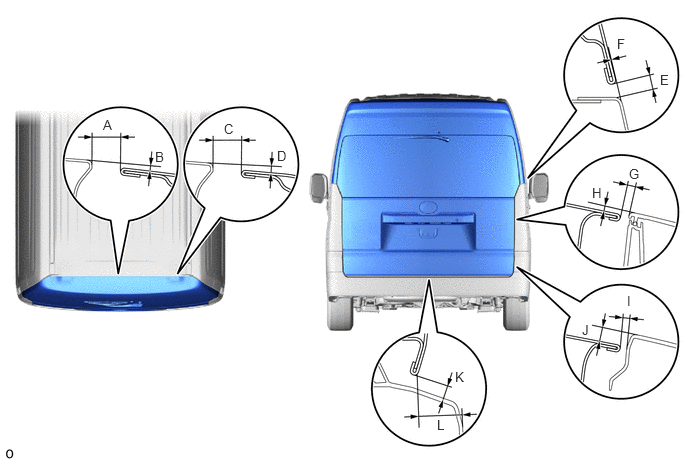
- Standard Clearance:
Area Measurement Area Measurement A 13.1 to 16.1 mm (0.516 to 0.634 in.) B 3.4 to 6.4 mm (0.134 to 0.252 in.) C 13.2 to 16.2 mm (0.520 to 0.638 in.) D 2.9 to 5.9 mm (0.114 to 0.232 in.) E 4.3 to 7.3 mm (0.169 to 0.287 in.) F -1.5 to 1.5 mm (-0.0591 to 0.0591 in.) G 3.5 to 7.5 mm (0.138 to 0.295 in.) H
(Reference)2.3 mm (0.0906 in.) I 3.5 to 7.5 mm (0.138 to 0.295 in.) J
(Reference)11.6 mm (0.457 in.) K
(Reference)8.0 mm (0.315 in.) L
(Reference)26.7 mm (1.051 in.)
- HINT:
-
Centering bolts are used to mount the door hinge to the vehicle body and door. The door cannot be adjusted with the centering bolts on. Substitute the centering bolts for standard bolts when making adjustments.