1GD-FTV EMISSION CONTROL EMISSION CONTROL SYSTEM DETAILS EGR PIPE AND EGR VALVE
CONSTRUCTION
Models with EGR Cooler
A water-cooled type No. 1 EGR cooler is used between the exhaust manifold and electric EGR control valve assembly. In the water-cooled type No. 1 EGR cooler, engine coolant flows through an eight-layered gas passage to cool down the EGR gas.
The No. 2 EGR valve assembly is used. The EGR gas passage is switched in 2 stages (opened or closed) by the No. 2 EGR valve assembly to optimize the temperature of the EGR gas.*1
*1: Models with No. 2 EGR valve assembly (for single actuator EGR bypass valve)
The No. 2 EGR valve assembly is used. The EGR gas passage is switched in 3 stages (opened, half opened or closed) by the No. 2 EGR valve assembly to optimize the temperature of the EGR gas.*2
*2: Models with No. 2 EGR valve assembly (for double actuator EGR bypass valve)
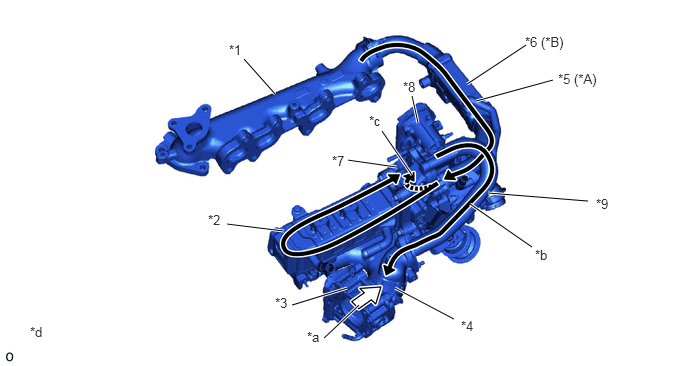
| *A | Models with EGR Pre-cooler | *B | Models without EGR Pre-cooler |
| *1 | Exhaust Manifold | *2 | No. 1 EGR Cooler |
| *3 | Diesel Throttle Body Assembly | *4 | Intake Manifold |
| *5 | EGR Pipe with Cooler Sub-assembly | *6 | No. 1 EGR Pipe Sub-assembly |
| *7 | No. 2 EGR Valve Assembly | *8 | Electric EGR Control Valve Assembly |
| *9 | No. 2 EGR Pipe | - | - |
| *a | Intake Air | *b | EGR Gas |
| *c | EGR Gas (through Bypass Passage) | *d | The illustration is a representative example. |
3-stage switching is determined by the operation combination of the No. 1 diaphragm and No. 2 diaphragm, which operate according to the No. 1 vacuum switching valve assembly and No. 2 vacuum switching valve assembly.
*2: Models with No. 2 EGR valve assembly (for double actuator EGR bypass valve)
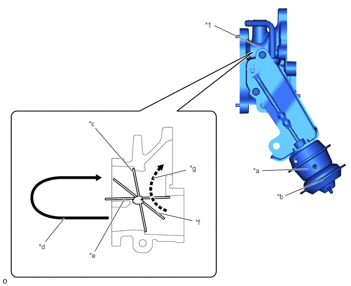
| *1 | No. 2 EGR Valve Assembly (for Double Actuator EGR Bypass Valve) | - | - |
| *a | No. 1 Diaphragm | *b | No. 2 Diaphragm |
| *c | Opened | *d | EGR Gas |
| *e | Closed | *f | Half Opened |
| *g | EGR Gas (through Bypass Passage) | - | - |
| Position | No. 1 Diaphragm | No. 2 Diaphragm |
|---|---|---|
| Opened | OFF | OFF |
| Half Opened | ON | OFF |
| Closed | ON | ON |
Models without EGR Cooler
EGR gas is sent to the intake manifold through the EGR pipe with cooler sub-assembly*1 or No. 1 EGR pipe sub-assembly*2, EGR valve adapter, EGR valve and No. 2 EGR pipe.
*1: Models with EGR pre-cooler
*2: Models without EGR pre-cooler
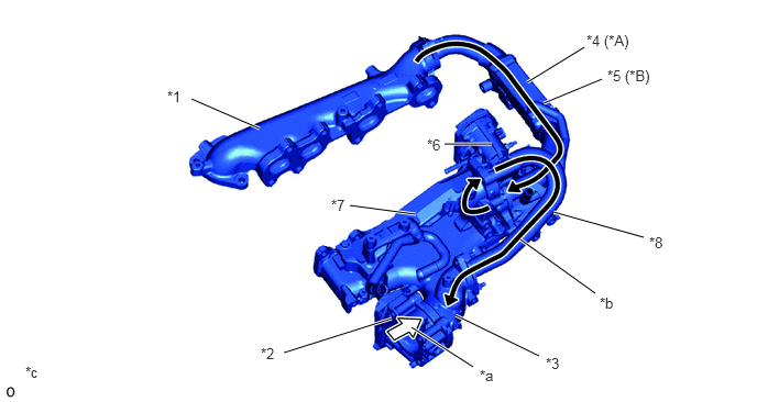
| *A | Models with EGR Pre-cooler | *B | Models without EGR Pre-cooler |
| *1 | Exhaust Manifold | *2 | Diesel Throttle Body Assembly |
| *3 | Intake Manifold | *4 | EGR Pipe with Cooler Sub-assembly |
| *5 | No. 1 EGR Pipe Sub-assembly | *6 | Electric EGR Control Valve Assembly |
| *7 | EGR Valve Adapter | *8 | No. 2 EGR Pipe |
| *a | Intake Air | *b | EGR Gas |
| *c | The illustration is a representative example. | - | - |