EXTERIOR PANELS / TRIM BODY STRUCTURE DETAILS SAFETY FEATURES
FUNCTION
Impact Absorbing Structure for Frontal Collision
To contain impact energy absorption within the short front overhang during frontal collisions, a straight member framework is used. As a result, a structure is created where most of the energy is absorbed by the front side member.
A straight front side member (*1 in illustration) is used to provide an axial compression mode during frontal collisions, providing superior impact energy absorption performance. The area to the rear of the center member (*2 in illustration) is also made straight, to support most of the high deformation load of the front side member (*1 in illustration) with only the side member.
To provide that the front side member (*1 in illustration) is axially compressed in a stable manner, an under member (side rail reinforcement sub-assembly rear (*4 in illustration)) is provided so that the radiator support (*3 in illustration) is not knocked over during the initial stage of a collision, provide deformation mode control during the initial stage of a collision.
To provide that the front side member (*1 in illustration) is axially compressed in a stable manner, an impact absorbing structure is used for the front frame assembly (*5 in illustration) so that the impact absorbing structure of the front frame assembly (*5 in illustration) does not contact the bottom of the vehicle during the second half of the collision.
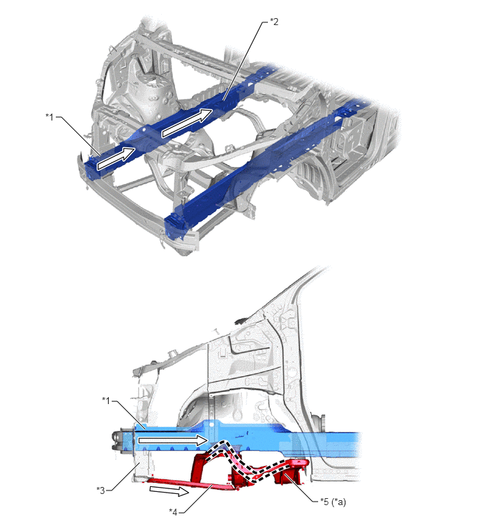
| *1 | Front Side Member | *2 | Center Member |
| *3 | Radiator Support | *4 | Side Rail Reinforcement Sub-assembly Rear LH |
| *5 | Front Frame Assembly | - | - |
| *a | Crushable Structure | - | - |

|
Front Impact Energy | - | - |
Impact Absorbing Structure for Side Collision
The floor side rail plate (*1 in illustration), No. 2 rear outrigger (*2 in illustration), floor side member (*3 in illustration) and front floor cross member No. 3 (*4 in illustration) are positioned so that their vertical walls are aligned to help efficiently transmitting and dispersing side impact energy, helping suppressing cabin deformation during side collisions.
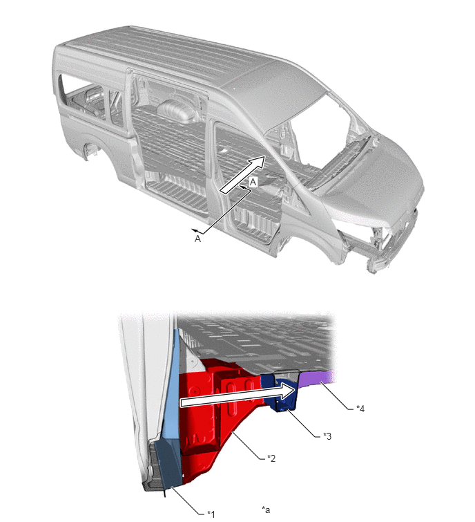
| *1 | Floor Side Rail Plate RH | *2 | No. 2 Rear RH Outrigger |
| *3 | Floor Side Member RH | *4 | Front Floor Cross Member No. 3 |
| *a | A - A Cross Section | - | - |
|
|
Side Impact Energy | - | - |
Impact Absorbing Structure for Pedestrian Head Injury
A leg attachment type hood panel reinforcement (*2 in illustration) is used for the front edge of the hood sub-assembly. Rigidity is ensured and the legs of the hood panel reinforcement (*2 in illustration) bend in the event of a collision with a pedestrian to help absorbing impact energy to contribute reducing the impact to the head of a pedestrian.
Slits (*d in illustration) are provided in the hood panel inner (*1 in illustration) and cutouts are provided between the mastic seating surfaces (*c in illustration) to contribute reducing the impact to the head of a pedestrian in the event of a collision with a pedestrian.
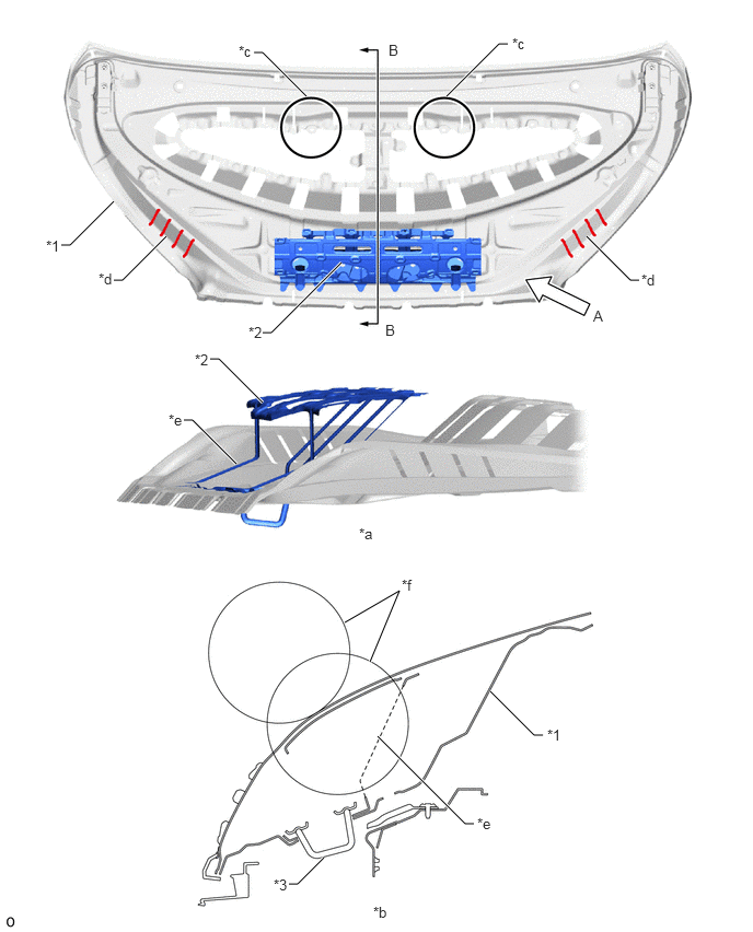
| *1 | Hood Panel Inner | *2 | Hood Panel Reinforcement |
| *3 | Hood Lock Hook | - | - |
| *a | View from A | *b | B - B Cross Section |
| *c | Cutouts between Mastic Seating Surfaces | *d | Slit |
| *e | Leg | *f | Head Form |
The rigidity of the cowl top ventilator louver sub-assembly (*1 in illustration) is ensured and a structure is used that easily helps reducing impact from the estimated collision direction of a pedestrian's head in the event of a collision with a pedestrian to help reducing the amount of impact delivered to the head of a pedestrian.
Notches (*c in illustration) are provided in the cowl top ventilator louver sub-assembly (*1 in illustration) to create an easily bending structure.
Small radius wedge (bent) shape (*d in illustration) is provided in the cowl top ventilator louver sub-assembly (*1 in illustration) to create an easily bending structure.
The dash panel RR (*2 in illustration) uses open cross sections, providing a structure that helps reducing impact.
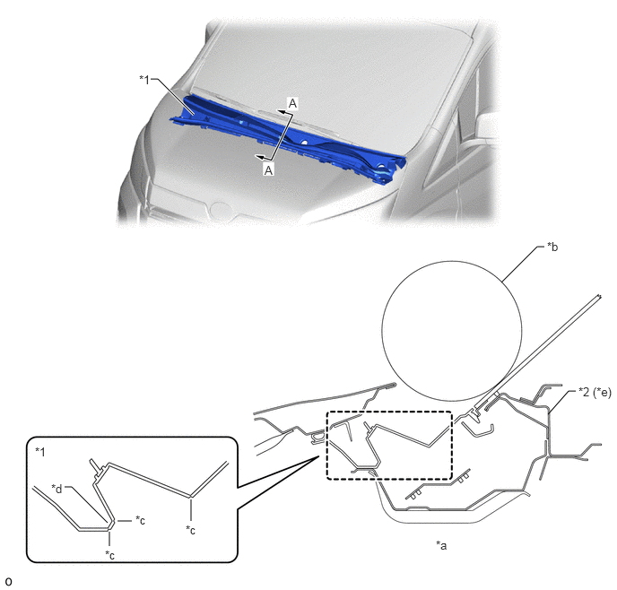
| *1 | Cowl Top Ventilator Louver Sub-assembly | *2 | Dash Panel RR |
| *a | A - A Cross Section | *b | Head Form |
| *c | Notch | *d | Wedge (Bent) Shape |
| *e | Open Structure | - | - |