PARK ASSIST / MONITORING PANORAMIC VIEW MONITOR SYSTEM CONTROL PANORAMIC VIEW MONITOR CONTROL
FUNCTION OF MAIN COMPONENTS
| Component | Function |
|---|---|
|
*1: Models with Toyota parking assist-sensor system *2: Models with blind spot monitor system |
|
| Front Television Camera Assembly | Sends a video signal of the area in front of the vehicle to the parking assist ECU. |
| Side Television Camera Assembly RH | Sends a video signal of the area to the right side of the vehicle to the parking assist ECU. |
| Side Television Camera Assembly LH | Sends a video signal of the area to the left side of the vehicle to the parking assist ECU. |
| Rear Television Camera Assembly | Sends a video signal of the area to the rear of the vehicle to the parking assist ECU. |
| Parking Assist ECU | ·
Combines video signals from the front, rear, left and right side television camera assemblies to create a seamless overhead image. ·
Calculates each guide line based on information signals from each ECU and sensor, combines the lines with the panoramic view and images from each television camera assembly, and outputs a video signal to the radio and display receiver assembly. ·
Turns each television camera assembly on and off according to the input shift position signal and panoramic view monitor switch signal. ·
Combines detection information with the currently displayed panoramic view monitor system screen according to signals from the clearance warning ECU assembly*1 or blind spot monitor sensor LH*2 and outputs a video signal to the radio and display receiver assembly. |
| Radio and Display Receiver Assembly | ·
Displays image information received from the parking assist ECU. ·
Outputs the screen status to the parking assist ECU, such as when the screen display mode switches and the automatic display mode turns on and off. |
| Panoramic View Monitor Switch | Switches the panoramic view monitor system screen display. |
| Steering Sensor | Detects the direction and angle of the steering wheel and sends the resulting signals to the parking assist ECU. |
| ECM | Sends the shift position signal to the parking assist ECU. |
| Skid Control ECU | Sends the vehicle speed signals to the parking assist ECU. |
| Main Body ECU (Multiplex Network Body ECU) | Sends the each door opening and closing signals to the parking assist ECU. |
| Clearance Warning ECU Assembly*1 | Sends the Toyota parking assist-sensor system information signal to the parking assist ECU. |
| Blind Spot Monitor Sensor LH*2 | Sends the RCTA function information signal to the parking assist ECU. |
| Central Gateway ECU (Network Gateway ECU) | Relays the signal between the CAN communication lines. |
| DLC3 | The Global TechStream (GTS) can be connected to read the Diagnostic Trouble Codes (DTCs) of malfunctions. |
OPERATING CONDITION
Manual display mode and automatic display mode are provided for the display method of the panoramic view monitor system.
Manual Display Mode
Manual display mode is a method of displaying the panoramic view monitor system screen according to the needs of the driver via operation of the panoramic view monitor switch.
The panoramic view monitor system is displayed by operating the panoramic view monitor switch when vehicle speed is approximately 20 km/h (12 mph) or less.
When the vehicle speed exceeds approximately 20 km/h (12 mph), the panoramic view monitor system screen ends and switches to display the navigation screen or information screen.
Automatic Display Mode
When starting off and stopping the vehicle in automatic display mode, it is possible to display the "panoramic view and wide front view" or "dual side view" automatically instead of by pressing the panoramic view monitor switch.
The automatic display mode can be set with the auto mode button displayed on the screen.
| Display | Screen Display Conditions | Objective | Assumed Situation |
|---|---|---|---|
| Display when starting off | Vehicle speed is 10 km/h (6 mph) or less and shift position is not P or R | Reminder to check surroundings | Check surroundings |
| Display when stopping vehicle | Shift position is not P or R and vehicle speed becomes 10 km/h (6 mph) or less | Reduce switch operations | ·
Check forward blind spot ·
Check inside blind spot ·
Check vehicle width ·
Check vehicle-to-vehicle distance |
FUNCTION
Panoramic View Monitor System Screen and Operation
Each screen of the panoramic view monitor system displays guide lines, estimated course lines, etc., to inform the driver of the tire positions and trajectories which cannot be directly seen from the driver seat, according to the selected screen display mode.
When the Toyota parking assist-sensor system detects an obstacle*1 or the RCTA function detects a vehicle approaching from the right or left at the rear of the vehicle*2, Toyota parking assist-sensor system information*1 or RCTA function information*2 is superimposed on the screen according to the selected screen display mode.
*1: Models with Toyota parking assist-sensor system
*2: Models with blind spot monitor system
Panoramic View and Wide Front View
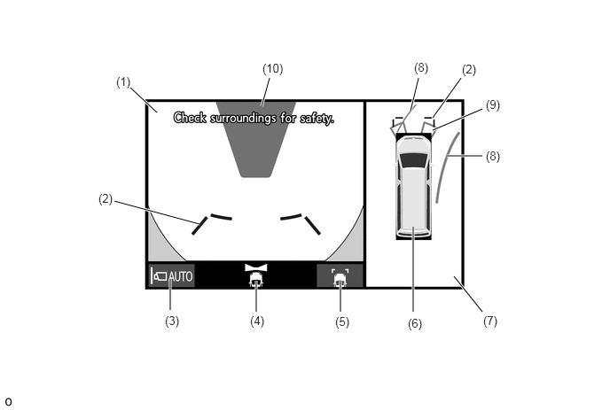
The panoramic view created by combining images from each television camera assembly and the image from the front television camera assembly are displayed simultaneously. The images assist the driver to confirm the safety of the surroundings and areas to the left and right of the vehicle at locations with poor visibility, such as intersections and T-junctions.
- HINT:
-
The illustration shown is an example only. The illustration may differ from the actual vehicle screen.
| Item | Description | |
|---|---|---|
|
*: Models with Toyota parking assist-sensor system |
||
| (1) | Wide Front View | An image captured by the front television camera assembly of the area in front of the vehicle. |
| (2) | Front Distance Guide Line (Blue) | These lines are distance guide lines showing the distance forward from the edge of the front bumper. [Approximately 1.0 m (3.3 ft.)] |
| (3) | Auto Mode Button | Is used to turn the automatic display mode on and off. When the automatic display mode is on, the switch indicator illuminates. |
| (4) | Camera Direction Display Vehicle Icon | Indicates that the wide front view is displayed. |
| (5) | Guide Line Switching Button | Changes the guide line display mode. |
| (6) | Panoramic View Vehicle Icon | Displays the vehicle position in the panoramic view. |
| (7) | Panoramic View | An overhead image of the vehicle created by combining images from the front, rear, left and right side television camera assemblies. |
| (8) | Forward Estimated Course Line (Yellow) | Displays the estimated course calculated from the steering angle.
(Displays when the steering wheel is operated more than 90° to either side.) |
| (9) | Toyota Parking Assist-sensor System Information* | If a stationary object is detected when the Toyota parking assist-sensor system is activated, the approximate distance between the vehicle and the stationary object is displayed. |
| (10) | Masking | Since the lens of the front television camera assembly may affect the perceived distance to objects in certain areas of the image, masking is used. |
Estimated Course Line Display Mode
The forward estimated course lines represent the estimated course of the vehicle. By turning the steering wheel so that no objects are within the estimated course lines, the driver can easily maneuver the vehicle around objects.
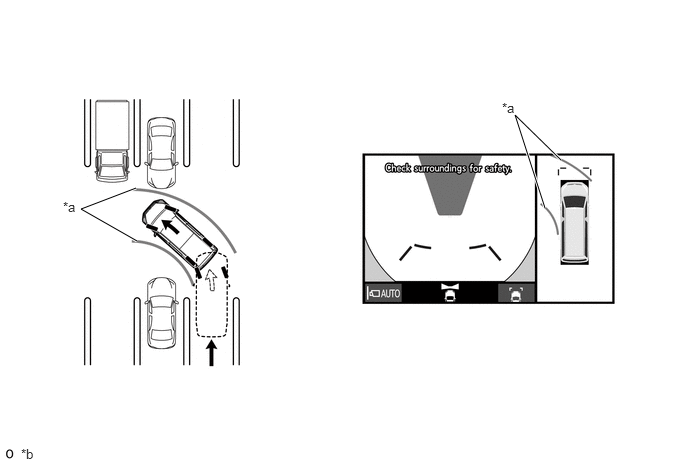
| *a | Forward Estimated Course Line | *b | The illustration shown is an example only. The illustration may differ from the actual vehicle screen. |
Distance Guide Line Display Mode
The front distance guide lines inform the driver of the vehicles relative location when driving into a parking space. By aligning the front distance guide lines with the end of the parking space and the parking space lines, the driver can easily position the vehicle within the parking space.
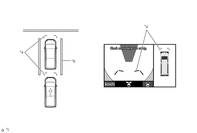
| *a | Front Distance Guide Line | *b | Parking Space Line |
| *c | The illustration shown is an example only. The illustration may differ from the actual vehicle screen. | - | - |
Dual Side View
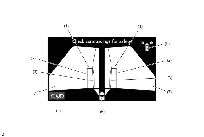
The images from the left and right side television camera assemblies are displayed simultaneously. As a result, this helps the driver confirm the safety of the areas to the sides of the vehicle and avoid contact with obstacles on narrow roads.
- HINT:
-
The illustration shown is an example only. The illustration may differ from the actual vehicle screen.
| Item | Description | |
|---|---|---|
|
*: Models with Toyota parking assist-sensor system |
||
| (1) | Front Distance Guide Line (Red) | These lines are distance guide lines showing the distance forward from the edge of the front bumper. [Approximately 0.5 m (1.6 ft.)] |
| (2) | Vehicle Width Parallel Line (Blue) | A vehicle width guide line including the outer rear view mirror assembly. |
| (3) | Front Tire Contact Line (Blue) | A guide line showing the front tire contact position. |
| (4) | Side View (Left Side) | An image captured by the side television camera assembly LH of the area from the left front corner of the vehicle. |
| (5) | Auto Mode Button | Is used to turn the automatic display mode on and off. When the automatic display mode is on, the switch indicator illuminates. |
| (6) | Camera Direction Display Vehicle Icon | Indicates that the dual side view is displayed. |
| (7) | Side View (Right Side) | An image captured by the side television camera assembly RH of the area from the right front corner of the vehicle. |
| (8) | Toyota Parking Assist-sensor System Information* | If a stationary object is detected when the Toyota parking assist-sensor system is activated, the approximate distance between the vehicle and the stationary object is displayed. |
Vehicle Width Parallel Line
The vehicle width parallel lines are used as a guide to know the approximate width of the vehicle including the outer rear view mirrors. By driving forward while steering so that the vehicle width parallel lines do not overlap actual obstacles, white lines, curbs, etc., the vehicle can avoid obstacles and drive close to objects on narrow roads.
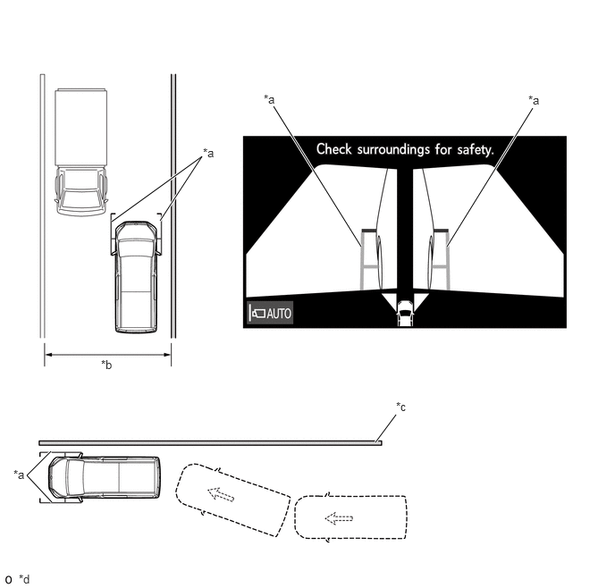
| *a | Vehicle Width Parallel Line | *b | Narrow Road, etc. |
| *c | Wall, Fence, etc. | *d | The illustration shown is an example only. The illustration may differ from the actual vehicle screen. |
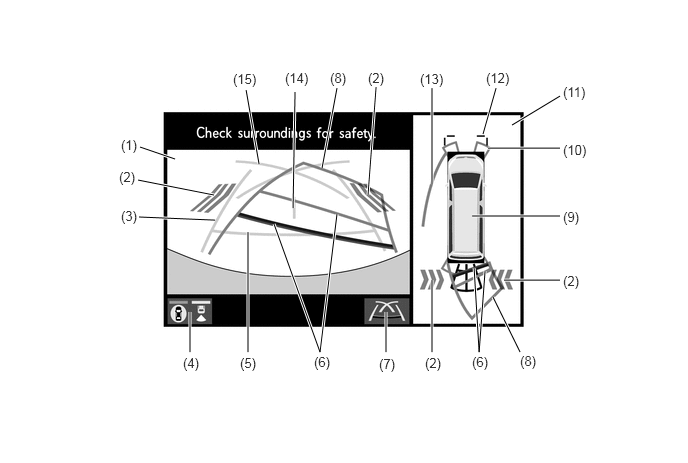
Panoramic View and Rear View
The panoramic view created by combining images from the front, rear, left and right side television camera assemblies and the image from the rear television camera assembly are displayed simultaneously. The images assist the driver to confirm the safety of the surroundings when operating the vehicle in reverse.
- HINT:
-
The illustration shown is an example only. The illustration may differ from the actual vehicle screen.
| Item | Description | |
|---|---|---|
|
*1: Models with blind spot monitor system *2: Models with Toyota parking assist-sensor system |
||
| (1) | Rear View | An image captured by the rear television camera assembly of the area to the rear of the vehicle. |
| (2) | RCTA Icon*1 | If a vehicle is detected when the RCTA function is activated, the direction of the approaching vehicle is displayed. |
| (3) | Rear Vehicle Width Guide Line (Blue) | Indicates the estimated vehicle width. |
| (4) | Display Mode Switching Button | Changes the display mode. |
| (5) | Rear Distance Guide Line (Blue) | These lines are distance guide lines showing the distance from the edge of the rear bumper. [Approximately 0.5 m (1.6 ft.)] |
| (6) | Rear Distance Guide Line (Yellow/Red) | These lines are distance guide lines showing the distance from the edge of the rear bumper. [Approximately 1.0 m (3.3 ft.): yellow, approximately 0.5 m (1.6 ft.): red] |
| (7) | Guide Line Switching Button | Changes the guide line display mode. |
| (8) | Rear Estimated Course Line (Yellow) | Moves in sync with the steering wheel to indicate the estimated reverse course of the vehicle. |
| (9) | Panoramic View Vehicle Icon | Displays the vehicle position in the panoramic view. |
| (10) | Toyota Parking Assist-sensor System Information*2 | If a stationary object is detected when the Toyota parking assist-sensor system is activated, the approximate distance between the vehicle and the stationary object is displayed. |
| (11) | Panoramic View | An overhead image of the vehicle created by combining images from the front, rear, left and right side television camera assemblies. |
| (12) | Front Distance Guide Line (Blue) | These lines are distance guide lines showing the distance forward from the edge of the front bumper. [Approximately 1.0 m (3.3 ft.)] |
| (13) | Side Estimated Course Line (Yellow) | ·
Displays the estimated course calculated from the steering angle. ·
Displays the estimated course on the outside of the steering direction. |
| (14) | Vehicle Center Guide Line (Blue) | Indicates the estimated position on the ground of the center of the vehicle. |
| (15) | Parking Assist Guide Line (Blue) | Indicates the path the vehicle will follow when the driver turns the steering wheel fully. |
Estimated Course Line Display Mode (Perpendicular Parking)
The estimated course lines inform the driver of the estimated course of the vehicle based on the current steering angle. When reversing, by turning the steering wheel so that the estimated course lines are correctly positioned with respect to the parking space lines, the driver can easily position the vehicle within the parking space. Also, the estimated course lines assist the driver to avoid obstacles.
The rear vehicle width guide lines can be used to determine whether the vehicle is parked straight in the parking space by confirming whether the parking space lines and rear vehicle width guide lines are crossed or parallel.
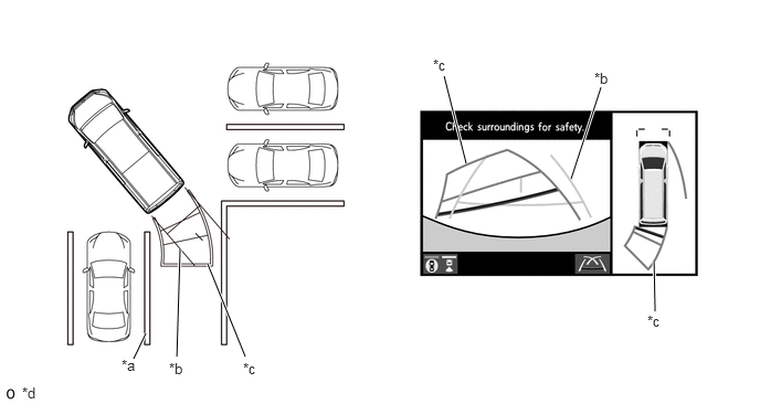
| *a | Parking Space Line | *b | Rear Vehicle Width Guide Line |
| *c | Rear Estimated Course Line | *d | The illustration shown is an example only. The illustration may differ from the actual vehicle screen. |
Estimated Course Line Display Mode (Parallel Parking)
The estimated course lines inform the driver of the estimated course of the vehicle based on the current steering angle. By turning the steering wheel so that the estimated course lines are correctly positioned with respect to the side of the road or parking space line, the driver can easily position the vehicle within the parking space. Also, the estimated course lines assist the driver to avoid obstacles.
The rear vehicle width guide lines can be used to determine whether the vehicle is parked straight in the desired parking position by confirming the status of the shoulder and parking space lines, etc., and rear vehicle width guide lines.
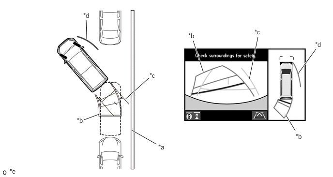
| *a | Shoulder and Parking Space Lines, etc. | *b | Rear Estimated Course Line |
| *c | Rear Vehicle Width Guide Line | *d | Side Estimated Course Line |
| *e | The illustration shown is an example only. The illustration may differ from the actual vehicle screen. | - | - |
Parking Assist Guide Line Display Mode (Perpendicular Parking)
The parking assist guide lines inform the driver of the course of the vehicle when the steering wheel is turned to full lock while driving in reverse. By driving the vehicle in reverse until the parking assist guide lines align with the parking space line, the vehicle can be guided to the position at which the driver should start turning the steering wheel.
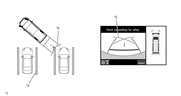
| *a | Parking Space Line | *b | Parking Assist Guide Line |
| *c | The illustration shown is an example only. The illustration may differ from the actual vehicle screen. | - | - |
Parking Assist Guide Line Display Mode (Parallel Parking)
The parking assist guide lines inform the driver of the course of the vehicle when the steering wheel is turned to full lock while driving in reverse. By driving the vehicle in reverse until the parking assist guide lines align with the side of the road or parking space line, the vehicle can be guided to the position at which the driver should start turning the steering wheel.
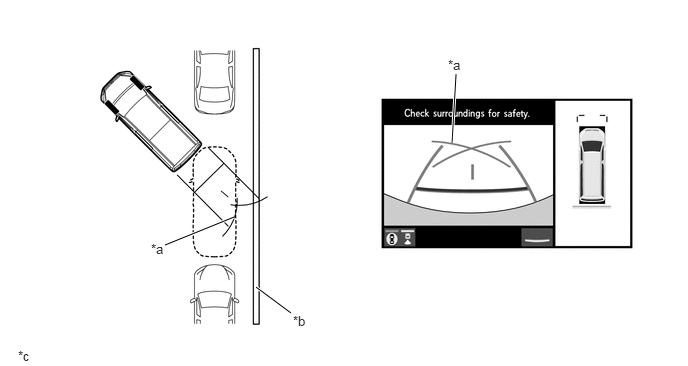
| *a | Parking Assist Guide Line | *b | Parking Space Line |
| *c | The illustration shown is an example only. The illustration may differ from the actual vehicle screen. | - | - |
Rear View
The image from the rear television camera assembly is displayed. The images assist the driver to confirm the safety of the surroundings when operating the vehicle in reverse.
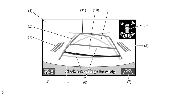
- HINT:
-
The illustration shown is an example only. The illustration may differ from the actual vehicle screen.
| Item | Description | |
|---|---|---|
|
*1: Models with blind spot monitor system *2: Models with Toyota parking assist-sensor system |
||
| (1) | Rear View | An image captured by the rear television camera assembly of the area to the rear of the vehicle. |
| (2) | Rear Vehicle Width Guide Line (Blue) | Indicates the estimated vehicle width. |
| (3) | RCTA Icon*1 | If a vehicle is detected when the RCTA function is activated, the direction of the approaching vehicle is displayed. |
| (4) | Display Mode Switching Button | Changes the display mode. |
| (5) | Rear Distance Guide Line (Blue) | These lines are distance guide lines showing the distance from the edge of the rear bumper. [Approximately 0.5 m (1.6 ft.)] |
| (6) | Rear Distance Guide Line (Yellow/Red) | These lines are distance guide lines showing the distance from the edge of the rear bumper. [Approximately 1.0 m (3.3 ft.): yellow, approximately 0.5 m (1.6 ft.): red] |
| (7) | Guide Line Switching Button | Changes the guide line display mode. |
| (8) | Toyota Parking Assist-sensor System Information*2 | If a stationary object is detected when the Toyota parking assist-sensor system is activated, the approximate distance between the vehicle and the stationary object is displayed. |
| (9) | Parking Assist Guide Line (Blue) | Indicates the path the vehicle will follow when the driver turns the steering wheel fully. |
| (10) | Vehicle Center Guide Line (Blue) | Indicates the estimated position on the ground of the center of the vehicle. |
| (11) | Rear Estimated Course Line (Yellow) | Moves in sync with the steering wheel to indicate the estimated reverse course of the vehicle. |
Panoramic View Monitor System Screen Transition
The panoramic view monitor system assists the driver to confirm the conditions around the vehicle while driving at low speeds and when parking.
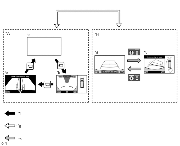
| *A | Except Shift Position R | *B | Shift Position R |
| *a | Navigation Display etc. | *b | Panoramic View and Wide Front View |
| *c | Dual Side View | *d | Rear View |
| *e | Panoramic View and Rear View | *f | Panoramic View Monitor Switch is Pressed. |
| *g | Shift Position Operation | *h | Display Mode Switching Button is Pressed. |
| *i | The illustration shown is an example only. The illustration may differ from the actual vehicle screen. | - | - |
DIAGNOSIS
In order to make system inspections easier to perform, a diagnosis function is used in consideration of serviceability. The DTCs of malfunctioning parts can be read by connecting the Global TechStream (GTS). Refer to the Repair Manual for details.