DOOR / HATCH SLIDE DOOR CLOSER SYSTEM DETAILS SLIDE DOOR LOCK
CONSTRUCTION
The slide door Lock assembly consists mainly of a closer motor, latch, pawl, open cable, various levers and various switches.
The slide door lock assembly fully closes the slide door automatically when the slide door is ajar.
When the slide door is fully closed, pull the open cable to disengage the latch in the slide door lock assembly.
The rear slide door lock assembly contains 4 switches to detect the locked state. The detection functions of the switches are the following:
| Detection Switch | Function |
|---|---|
| Half-latch Switch | Turns on from the time the latch is released, until just before it is at the half latch position, in order to detect the position of the latch. |
| Full-latch Switch | Turns off when the latch is in the full latch state, in order to detect the fully closed position of the latch. |
| Pawl Switch | Detects the position of the pawl, turns on when the latch is fully closed, and turns off when the latch is rotating. |
| Neutral Position Switch (Close) | Detects the active lever close operating range, and turns off when the active lever returns to its initial position. |
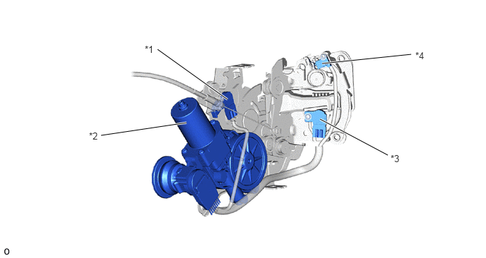
| *1 | Neutral Position Switch | *2 | Closer Motor |
| *3 | ·
Half-latch Switch ·
Full-latch Switch |
*4 | Pawl Switch |
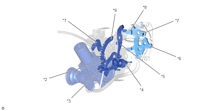
| *1 | Neutral Position Switch | *2 | Active Lever |
| *3 | Pinion | *4 | Passive Lever |
| *5 | Open Lever | *6 | Latch |
| *7 | Pawl | *8 | Lift Lever |
| *9 | Release Lever | - | - |
Neutral Position Switch
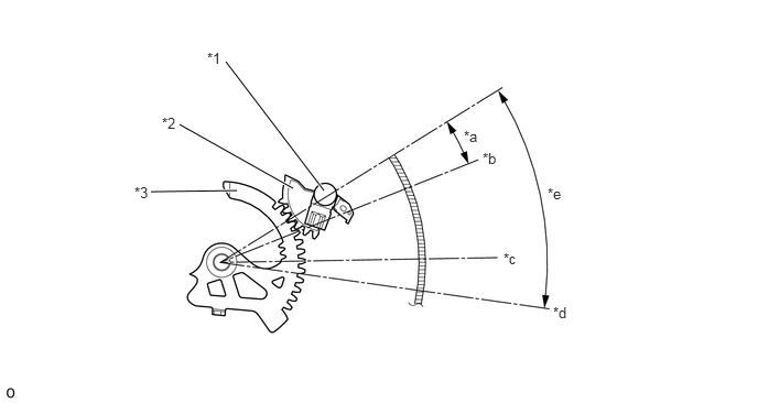
| *1 | Neutral Position Switch | *2 | Neutral Position Switch Gear |
| *3 | Active lever | - | - |
| *a | Half Latch Range | *b | Half Latch Position |
| *c | Full Latch Position | *d | Over Latch Position |
| *e | Close Operating Range | - | - |
Half Latch, Full Latch Switch and Pawl Switch
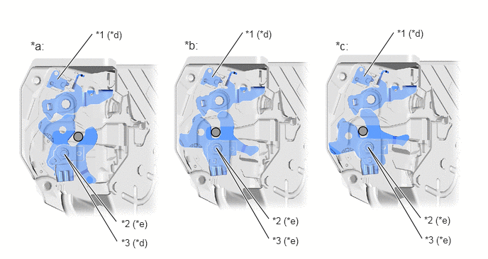
| *1 | Pawl Switch | *2 | Half-latch Switch |
| *3 | Full-latch Switch | - | - |
| *a | Half Latch | *b | Full Latch |
| *c | Over Latch | *d | On |
| *e | Off | - | - |
OPERATION
Close Operation
The closer motor rotates according to each type of switch signal. When the closer motor causes the pinion (*2 in illustration) to start rotating, first, the active lever (*1 in illustration) that is engaged with the pinion (*2 in illustration) rotates, raising the passive lever (*3 in illustration).
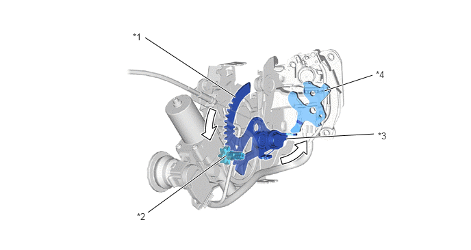
| *1 | Active Lever | *2 | Pinion |
| *3 | Passive Lever | *4 | Latch |
The raised passive lever (*3 in illustration) presses the latch (*4 in illustration) and the rotation of the latch (*4 in illustration) moves the slide door from ajar to fully closed.
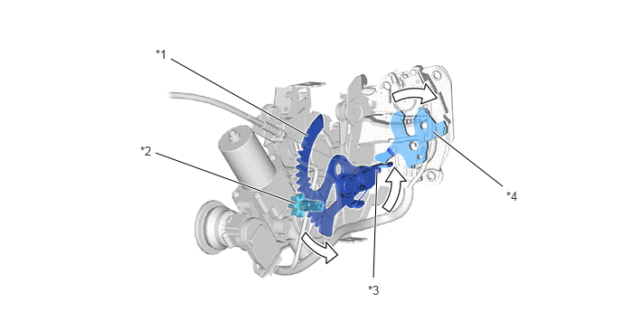
| *1 | Active Lever | *2 | Pinion |
| *3 | Passive Lever | *4 | Latch |
After the latch (*4 in illustration) fully closes, the closer motor operates in reverse, operating the active lever (*1 in illustration) in reverse via the pinion. Afterward, when the active lever (*1 in illustration) returns to its initial position, the closer motor stops and the close operation completes.
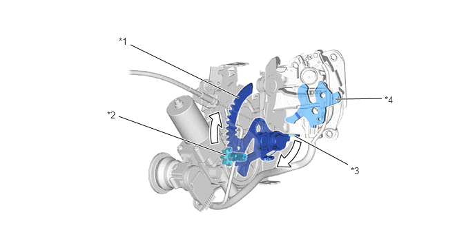
| *1 | Active Lever | *2 | Pinion |
| *3 | Passive Lever | *4 | Latch |
Release Operation
When an occupant operates the inside handle or outside handle, the slide door closer open cable assembly (*2 in illustration) is pulled via the slide door lock remote control assembly. Next, the slide door closer open cable assembly (*2 in illustration) pulls and rotates the open lever (*1 in illustration), directly pressing the lift lever (*5 in illustration) and releasing the connection between the pawl and latch. The above operations complete the release operation.
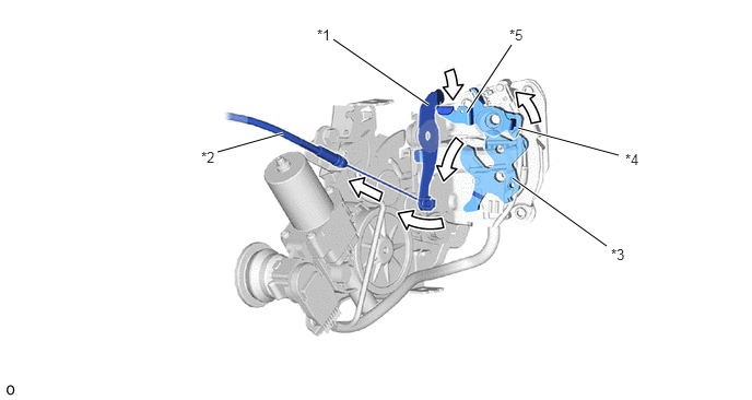
| *1 | Open Lever | *2 | Slide Door Closer Open Cable Assembly |
| *3 | Latch | *4 | Pawl |
| *5 | Lift Lever | - | - |