Home › Vehicle Interior › HEATING / AIR CONDITIONING › AIR CONDITIONING SYSTEM › from 2019.06
NM35X0E _58 Vehicle Interior _078578 HEATING / AIR CONDITIONING _0381952 AIR CONDITIONING SYSTEM DE DETAILS F

HEATING / AIR CONDITIONING  AIR CONDITIONING SYSTEM  DETAILS  REAR AIR CONDITIONING UNIT  


CONSTRUCTION


a.

Rear Cooling Unit Assembly (Models with Automatic Rear Air Conditioning System)

i.

The rear cooling unit assembly consists of the evaporator sub-assembly (rear), rear evaporator fin sensor (no. 2 cooler thermistor), rear blower motor with fan sub-assembly, blower motor control and heater radiator unit sub-assembly.


ii.

A Refrigerant Stream (RS) type evaporator is used.


iii.

A Straight Flow Aluminum-II (SFA-II) heater core that is compact and offers advanced performance is used.
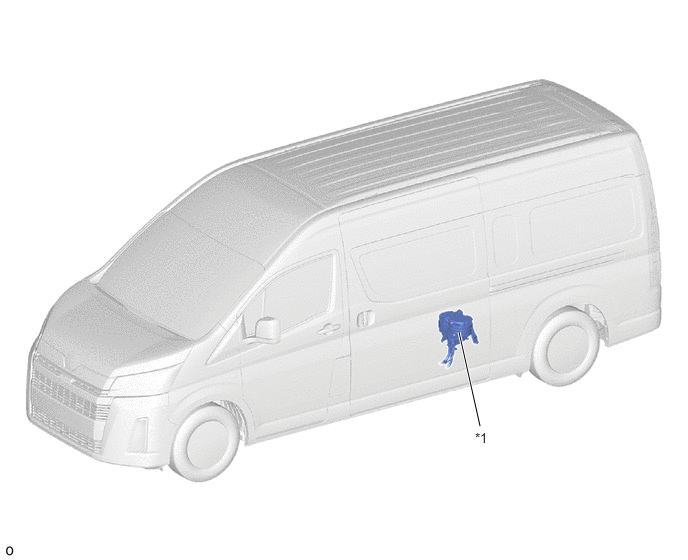
Rear Cooling Unit Layout Parts Location
Y248009C01
5.698,4.5 5.021,2.323 true 5.635,4.51 5.948,4.708 0.313,0.198 10 false *1
*1 Rear Cooling Unit Assembly - -


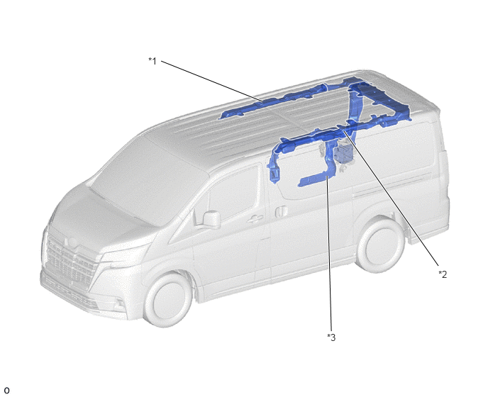
Duct Layout Parts Location
Y248011C01
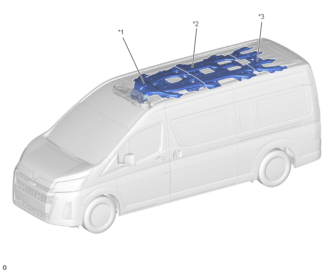
6.438,3.906 5.052,1.927 true 2.365,0.896 3.854,1.49 true 4.802,2.583 4.865,4.865 true 2.177,0.813 2.49,1.01 0.313,0.198 10 false *1 4.802,4.875 5.115,5.073 0.313,0.198 10 false *3 6.438,3.948 6.75,4.146 0.313,0.198 10 false *2
*1 Roof Side Register Duct RH *2 Roof Side Register Duct LH
*3 Rear Footwell Register Duct - -


b.

Rear Cooling Unit Assembly (Models with Rear Cooler System)

i.

The rear cooling unit consists of the evaporator sub-assembly (rear), rear evaporator fin sensor (no. 2 cooler thermistor), rear blower motor with fan sub-assembly, rear cooler blower resistor*1 and blower motor control*2.


ii.

A Beneficial Refrigerant Stream (BRS) type evaporator is used.

*1: DX grade

*2: GL grade and VX grade
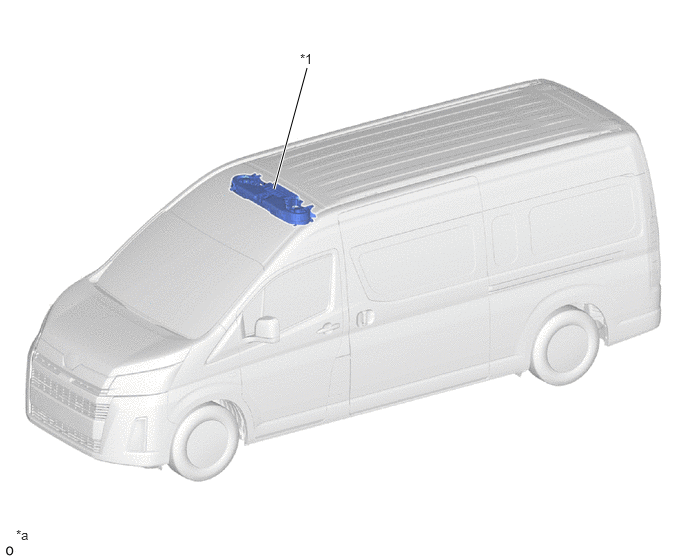

Rear Cooling Unit Layout Parts Location
Y243083C02
2.854,1.969 3.198,0.708 true 3.125,0.531 3.438,0.729 0.313,0.198 10 false *1 0.167,5.49 0.479,5.688 0.313,0.198 10 false *a
*1 Rear Cooling Unit Assembly - -
*a The illustration shown is an example only. - -


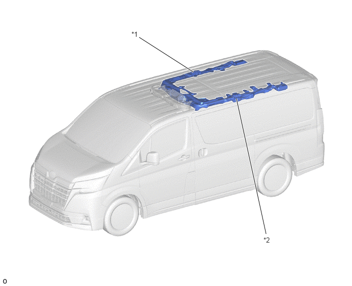
Duct Layout Parts Location (VX Grade with Standard Roof Models)
Y248010C01
3.938,1.469 2.833,0.76 true 5.417,4.771 4.813,2.01 true 2.677,0.615 2.99,0.813 0.313,0.198 10 false *1 5.365,4.813 5.677,5.01 0.313,0.198 10 false *2
*1 Roof Side Register Duct RH (No. 1 Cooler Air Duct) *2 Roof Side Register Duct LH (No. 1 Cooler Air Duct)


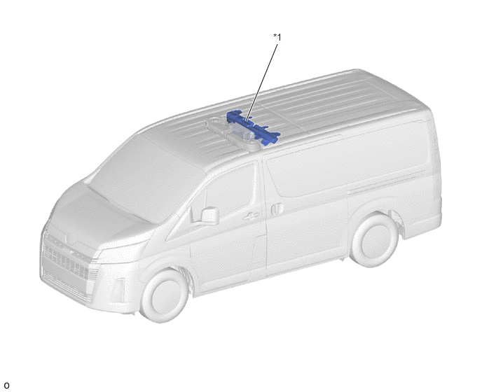
Duct Layout Parts Location (Except VX Grade with Standard Roof Models)
Y243108C01
3.656,1.802 4.125,0.656 true 4.063,0.469 4.375,0.667 0.313,0.198 10 false *1
*1 Roof Air Duct (No. 1 Cooler Air Duct) - -


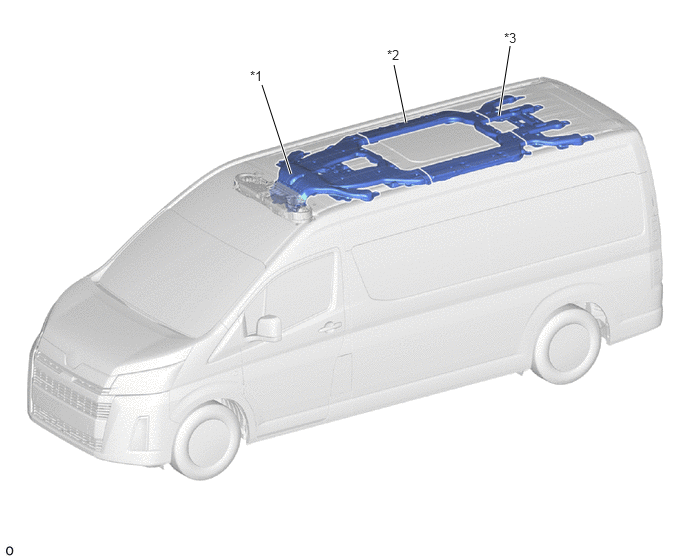
Duct Layout Parts Location (High Roof Models with Roof Window Glass)
Y243109C01
2.729,0.885 3.031,1.813 true 4.104,0.677 4.229,1.281 true 5.313,0.479 5.198,1.208 true 2.604,0.708 2.917,0.906 0.313,0.198 10 false *1 4.031,0.49 4.344,0.688 0.313,0.198 10 false *2 5.25,0.313 5.563,0.51 0.313,0.198 10 false *3
*1 Front Roof Air Duct (No. 1 Cooler Air Duct) *2 Center Roof Air Duct (No. 1 Cooler Air Duct)
*3 Rear Roof Air Duct (No. 1 Cooler Air Duct) - -


Duct Layout Parts Location (High Roof Models without Roof Window Glass)
Y243084C01
3.094,1.792 2.635,0.802 true 4.125,1.458 4.219,0.604 true 5.521,1.323 5.615,0.469 true 2.531,0.604 2.844,0.802 0.313,0.198 10 false *1 4.135,0.427 4.448,0.625 0.313,0.198 10 false *2 5.542,0.271 5.854,0.469 0.313,0.198 10 false *3
*1 Front Roof Air Duct (No. 1 Cooler Air Duct) *2 Center Roof Air Duct (No. 1 Cooler Air Duct)
*3 Rear Roof Air Duct (No. 1 Cooler Air Duct) - -


c.

Rear Heater Unit (Heater Assembly) (Models with Manual Rear Heater System)

i.

The rear heater unit consists of the rear heater unit sub-assembly, rear blower motor sub-assembly and rear heater blower resistor.


ii.

A Straight Flow Aluminum-II (SFA-II) heater core that is compact and offers advanced performance is used.
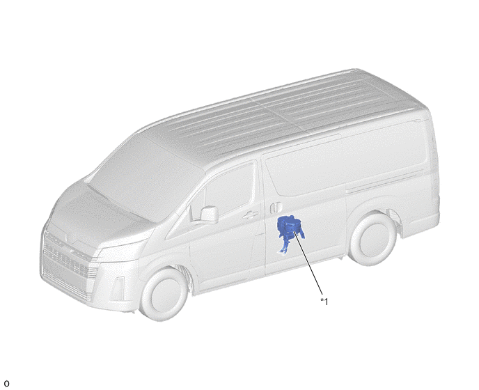
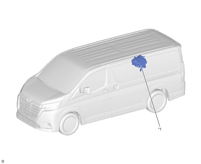
Rear Heater Unit Layout Parts Location (Standard Roof Models)
Y243086C01
4.823,4.406 4.396,3.458 true 4.792,4.427 5.104,4.625 0.313,0.198 10 false *1
*1 Rear Heater Assembly - -


Rear Heater Unit Layout Parts Location (High Roof Models)
Y243112C01
5,4.438 4.781,3.458 true 4.948,4.479 5.26,4.677 0.313,0.198 10 false *1
*1 Rear Heater Assembly - -


OPERATION


a.

Mode Position and Door Operation (Models with Automatic Rear Air Conditioning System)
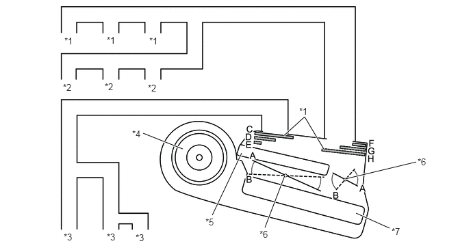
Y248030C01
4.313,2.073 4.635,1.781 4.635,1.781 4.938,2.292 true 5.417,3.25 5.927,3.479 true 4.333,2.677 4.031,3.469 true 5.25,2.729 6.333,2.469 true 3.677,2.333 3.229,3.281 true 2.781,2.271 2.177,2.031 true 0.979,0.542 1.292,0.74 0.313,0.198 10 false *1 1.625,0.531 1.938,0.729 0.313,0.198 10 false *1 2.271,0.542 2.583,0.74 0.313,0.198 10 false *1 0.958,1.25 1.271,1.448 0.313,0.198 10 false *2 1.594,1.24 1.906,1.438 0.313,0.198 10 false *2 2.25,1.26 2.563,1.458 0.313,0.198 10 false *2 0.969,3.531 1.281,3.729 0.313,0.198 10 false *3 1.625,3.531 1.938,3.729 0.313,0.198 10 false *3 2.063,3.542 2.375,3.74 0.313,0.198 10 false *3 2.01,1.958 2.323,2.156 0.313,0.198 10 false *4 3.125,3.302 3.438,3.5 0.313,0.198 10 false *5 3.948,3.49 4.26,3.688 0.313,0.198 10 false *6 5.958,3.448 6.271,3.646 0.313,0.198 10 false *7 6.354,2.385 6.667,2.583 0.313,0.198 10 false *6 4.552,1.615 4.865,1.813 0.313,0.198 10 false *1
*1 Roof Side Register Duct RH *2 Roof Side Register Duct LH
*3 Rear Footwell Register Duct *4 Rear Blower Motor with Fan Sub-assembly
*5 Heater Radiator Unit Sub-assembly *6 Air Mix Control Damper
*7 Evaporator Sub-assembly (Rear) *8 Mode Switching Damper


Mode Position and Damper Operation
Control Damper Operation Position Damper Position Operation
Air Mix Control Damper MAX COLD to MAX HOT Temperature Setting A - B Varies the mixture ratio of warm air and cool air in order to continuously regulate the temperature between max hot and max cool.
Air Outlet Control Damper FACE C
F
Air blows out of the roof side registers.
BI-LEVEL D
G
Air blows out of the roof side registers and rear footwell registers.
FOOT E
H
Air blows out of the rear footwell registers.


b.

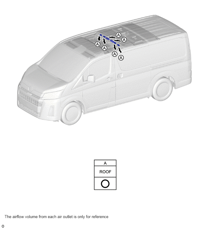
Rear Cooling Unit Assembly (Models with Automatic Rear Air Conditioning System)
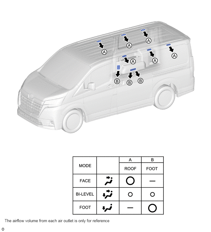
Y248013E01
0.156,7.396 3.75,7.813 3.594,0.417 10 false The airflow volume from each air outlet is only for reference


c.

Rear Cooling Unit Assembly (Models with Rear Cooler System)

i.

Air Outlets and Airflow Volume (VX Grade with Standard Roof Models)
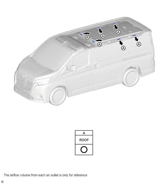
Y248012E01
0.156,7.396 3.75,7.813 3.594,0.417 10 false The airflow volume from each air outlet is only for reference


ii.

Air Outlets and Airflow Volume (Except VX Grade with Standard Roof Models)
Y243110E01
0.156,7.354 3.75,7.771 3.594,0.417 10 false The airflow volume from each air outlet is only for reference


iii.

Air Outlets and Airflow Volume (High Roof Models with Roof Window Glass)
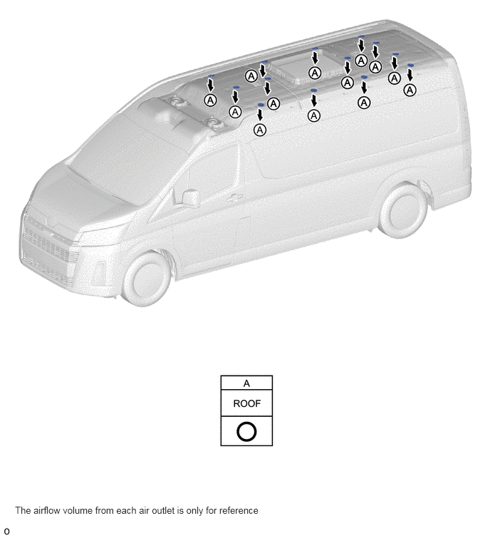
Y243111E01
0.219,7.375 3.76,7.75 3.542,0.375 10 false The airflow volume from each air outlet is only for reference


iv.

Air Outlets and Airflow Volume (High Roof Models without Roof Window Glass)
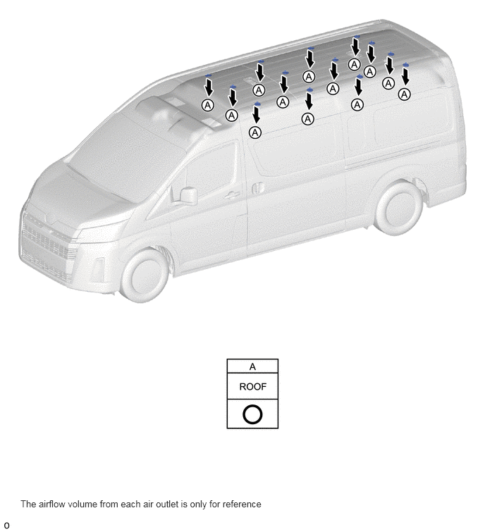
Y243085E01
0.302,7.365 3.865,7.708 3.563,0.344 10 false The airflow volume from each air outlet is only for reference