HEATING / AIR CONDITIONING AIR CONDITIONING SYSTEM DETAILS REAR AIR CONDITIONING CONTROL PANEL
CONSTRUCTION
No. 2 Air Conditioning Control Assembly (DX Grade)
The blower level of the rear cooling unit*1 and heater assembly*2 can be changed with the heater control and accessory assembly.
The No. 2 air conditioning control assembly is positioned in the center of the instrument panel and is used from the front to operate the manual rear cooler system*1 or manual rear heater system*2.
*1: Models with manual rear cooler system
*2: Models with manual rear heater system
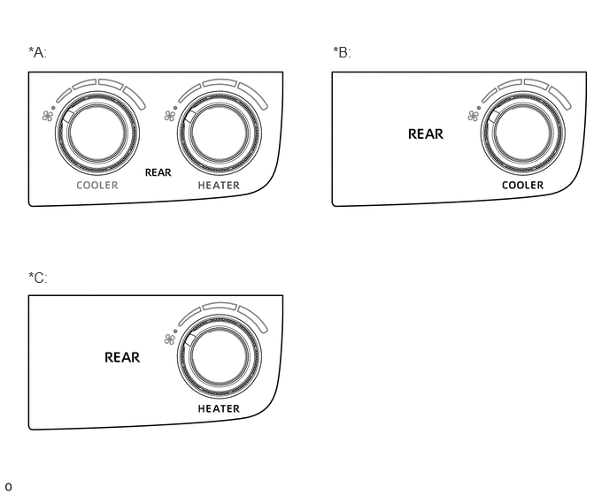
| *A | Models with Manual Rear Cooler System and Manual Rear Heater System | *B | Models with Manual Rear Cooler System |
| *C | Models with Manual Rear Heater System | - | - |
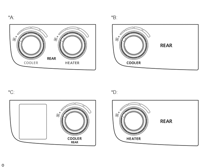
| *A | Models with Manual Rear Cooler System and Manual Rear Heater System | *B | Models with Manual Rear Cooler System |
| *C | Models with Manual Rear Cooler System and Seat Belt Warning | *D | Models with Manual Rear Heater System |
No. 2 Air Conditioning Control Assembly (GL Grade)
The blower level of the rear cooling unit and heater assembly* can be changed with the No. 2 air conditioning control assembly.
The No. 2 air conditioning control assembly is positioned in the center of the instrument panel and is used from the front to operate the manual rear cooler system or manual rear heater system*.
*: Models with manual rear heater system
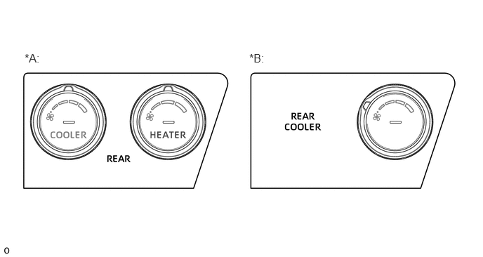
| *A | Models with Manual Rear Cooler System and Manual Rear Heater System | *B | Models with Manual Rear Cooler System |
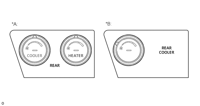
| *A | Models with Manual Rear Cooler System and Manual Rear Heater System | *B | Models with Manual Rear Cooler System |
Integration Control and Panel Assembly (VX Grade)
The switches that operate the automatic rear cooler system*1 and automatic rear air conditioning system*2 are positioned in the integration control and panel assembly. A momentary switch is used for each switch.
A Liquid Crystal Display (LCD) is positioned to display the temperature setting*2, air outlet mode*2 and blower level.
*1: Models with automatic rear cooler system
*2: Models with automatic rear air conditioning system
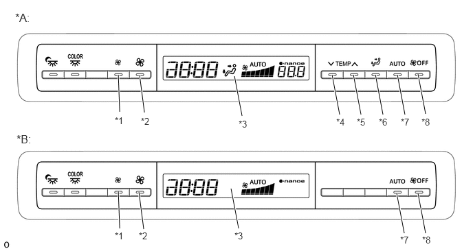
| *A | Models with Automatic Rear Air Conditioning System | *B | Models with Automatic Rear Cooler System |
| *1 | Blower Level Setting Switch (DOWN) | *2 | Blower Level Setting Switch (UP) |
| *3 | Liquid Crystal Display (LCD) | *4 | Temperature Setting Switch (DOWN) |
| *5 | Temperature Setting Switch (UP) | *6 | Mode Setting Switch |
| *7 | AUTO Switch | *8 | Blower OFF Switch |
Integration Control and Panel Assembly (GL Grade)
The blower level of the rear cooling unit and heater assembly* can be changed with the integration control and panel assembly.
The integration control and panel assembly is positioned in the center of the roof headlining and is used from the rear to operate the manual rear cooler system or manual rear heater system*.
*: Models with manual rear heater system
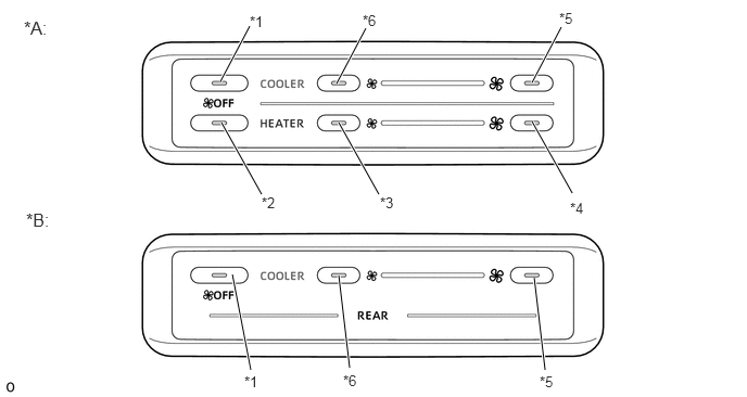
| *A | Models with Manual Rear Heater System | *B | Models without Manual Rear Heater System |
| *1 | Blower OFF Switch (Cooler) | *2 | Blower OFF Switch (Heater) |
| *3 | Blower Level Down Switch (Heater) | *4 | Blower Level Up Switch (Heater) |
| *5 | Blower Level Up Switch (Cooler) | *6 | Blower Level Down Switch (Cooler) |