HEATING / AIR CONDITIONING AIR CONDITIONING SYSTEM DETAILS AIR CONDITIONING UNIT
CONSTRUCTION
The air conditioning unit consists of the No. 1 cooler evaporator sub-assembly*1, heater radiator unit sub-assembly*2, servo motors, evaporator temperature sensor (No. 1 cooler thermistor)*1 and blower motor with fan sub-assembly.
A Beneficial Refrigerant Stream (BRS) type evaporator is used.*3
A Cold Storage (CS) type evaporator is used.*4
A Straight Flow Aluminum-II (SFA-II) heater core that is compact and offers advanced performance is used.
- HINT:
-
*1: On models with manual heater system and boost vent system, No. 1 cooler evaporator sub-assembly and evaporator temperature sensor has been provided, but is not used.
-
*2: Models with automatic air conditioning system, manual air conditioning system or manual heater system
-
*3: Models without stop and start system
-
*4: Models with stop and start system
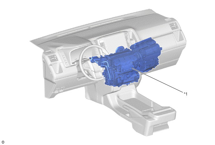
| *1 | Air Conditioning Unit Assembly | - | - |
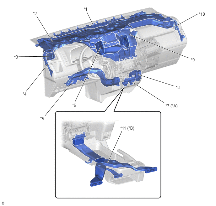
| *A | Models with Front Center Footwell Duct | *B | Models with Rear Footwell Duct |
| *1 | Center Defroster Duct (RR Defroster Nozzle) | *2 | Heater to Register Duct
·
Driver Side Side Defroster Duct ·
Front Passenger Side Side Defroster Duct |
| *3 | Driver Side Side Register Duct (No. 1 Heater to Register Duct) | *4 | Driver Side Side Defroster Duct (No. 1 Side Defroster Nozzle Duct) |
| *5 | Driver Side Footwell Duct (Air Duct) | *6 | Driver Side Center Register Duct (No. 2 Heater to Register Duct) |
| *7 | Center Footwell Duct (Air Duct) | *8 | Front Passenger Side Footwell Duct (Air Duct) |
| *9 | No. 3 Heater to Register Duct
·
Front Passenger Side Center Register Duct ·
Front Passenger Side Side Register Duct |
*10 | Front Passenger Side Side Defroster Duct (No. 2 Side Defroster Nozzle Duct) |
| *11 | RR Air Duct
·
Rear Passenger Left Side Footwell Duct ·
Rear Passenger Right Side Footwell Duct ·
Rear Center Footwell Duct |
- | - |
OPERATION
Mode Position and Door Operation
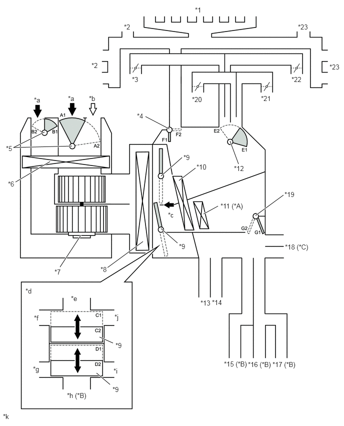
| *A | Models with PTC Heater | *B | Models with Rear Footwell Duct |
| *C | Models with Front Center Footwell Duct | - | - |
| *1 | Center Defroster Duct | *2 | Driver Side Side Defroster Duct |
| *3 | Driver Side Side Register Duct | *4 | DEF Door |
| *5 | Fresh/Recirculation Mode Door Switching Servo Motor | *6 | Air Refiner Element (Clean Air Filter) |
| *7 | Blower Motor with Fan Sub-assembly | *8 | No. 1 Cooler Evaporator Sub-assembly |
| *9 | Air Mix Door | *10 | Heater Radiator Unit Sub-assembly |
| *11 | PTC Heater (Quick Heater Assembly) | *12 | FACE Door |
| *13 | Driver Side Footwell Duct | *14 | Front Passenger Side Footwell Duct |
| *15 | Rear Passenger Left Side Footwell Duct | *16 | Rear Center Footwell Duct |
| *17 | Rear Passenger Right Side Footwell Duct | *18 | Front Center Footwell Duct |
| *19 | FOOT Door | *20 | Driver Side Center Register Duct |
| *21 | Front Passenger Side Center Register Duct | *22 | Front Passenger Side Side Register Duct |
| *23 | Front Passenger Side Side Defroster Duct | - | - |
| *a | Recirculation Air | *b | Fresh Air |
| *c | [A] View | *d | Illustration Image View from [A] |
| *e | Defroster Duct | *f | Driver Side Register Duct |
| *g | Driver Side Footwell Duct | *h | Center Footwell Duct |
| *i | Front Passenger Side Footwell Duct | *j | Front Passenger Side Register Duct |
| *k | This illustration is a diagram of the door position in each mode. The actual position of parts and number of door may vary from the actual vehicle. | - | - |
| Control Damper | Operation Position | Damper Position | Operation |
|---|---|---|---|
| Air Inlet Control Damper | FRESH | A1
B2 |
Allows fresh air to enter. |
| RECIRCULATION | A2
B1 |
Causes internal air to recirculate. | |
| Air Mix Control Damper | MAX COLD to MAX HOT Temperature Setting | C1 - C2
D1 - D2 |
Separates or integrates the upper layer and lower layer in response to the control conditions to control the inside-and-outside dual air layers. |
| Air Outlet Control Damper | FACE | E1
F2 G2 |
Blows air out from the following registers.
·
Center Registers ·
Side Registers |
| BI-LEVEL | E1- E2
F2 G1 - G2 |
·
Blows air out from the following registers. -
Center Registers -
Side Registers -
Footwell Registers |
|
| FOOT | E1 - E2
F1 - F2 G1 - G2 |
·
Blows air out from the following registers. -
Footwell Registers ·
Blows small amounts of air out from the following registers. -
Side Registers -
Center Defrosters -
Side Registers |
|
| FOOT/DEF | E1 - E2
F1 - F2 G1 - G1 |
·
Blows air out from the following registers. -
Footwell Registers -
Center Defroster ·
Blows small amounts of air out from the following registers. -
Side Registers -
Side Defrosters |
|
| DEF | E1 - E2
F1 G2 |
Blows air out from the following registers.
·
Side Registers ·
Center Defrosters ·
Side Defrosters |
Mode Position and Door Operation
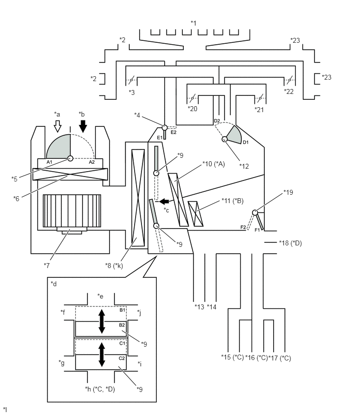
| *A | Models with Manual Air Conditioning System or Manual Heater System | *B | Models with PTC Heater |
| *C | Models with Rear Footwell Duct | *D | Models with Front Center Footwell Duct |
| *1 | Center Defroster Duct | *2 | Driver Side Side Defroster Duct |
| *3 | Driver Side Side Register Duct | *4 | DEF Door |
| *5 | Fresh/Recirculation Mode Door Switching Servo Motor | *6 | Air Refiner Element (Clean Air Filter) |
| *7 | Blower Motor with Fan Sub-assembly | *8 | No. 1 Cooler Evaporator Sub-assembly |
| *9 | Air Mix Door | *10 | Heater Radiator Unit Sub-assembly |
| *11 | PTC Heater (Quick Heater Assembly) | *12 | FACE Door |
| *13 | Driver Side Footwell Duct | *14 | Front Passenger Side Footwell Duct |
| *15 | Rear Passenger Left Side Footwell Duct | *16 | Rear Center Footwell Duct |
| *17 | Rear Passenger Right Side Footwell Duct | *18 | Front Center Footwell Duct |
| *19 | FOOT Door | *20 | Driver Side Center Register Duct |
| *21 | Front Passenger Side Center Register Duct | *22 | Front Passenger Side Side Register Duct |
| *23 | Front Passenger Side Side Defroster Duct | - | - |
| *a | Recirculation Air | *b | Fresh Air |
| *c | [A] View | *d | Illustration Image View from [A] |
| *e | Defroster Duct | *f | Driver Side Register Duct |
| *g | Driver Side Footwell Duct | *h | Center Footwell Duct or Rear Footwell Duct |
| *i | Front Passenger Side Footwell Duct | *j | Front Passenger Side Register Duct |
| *k | On models with manual heater system, No. 1 cooler evaporator sub-assembly has been provided, but is not used. | *l | This illustration is a diagram of the door position in each mode. The actual position of parts and number of door may vary from the actual vehicle. |
| Control Damper | Operation Position | Damper Position | Operation |
|---|---|---|---|
| Air Inlet Control Damper | FRESH | A1 | Allows fresh air to enter. |
| RECIRCULATION | A2 | Causes internal air to recirculate. | |
| Air Mix Control Damper | MAX COLD to MAX HOT Temperature Setting | B1 - B2
C1 - C2 |
Separates or integrates the upper layer and lower layer in response to the control conditions to control the inside-and-outside dual air layers. |
| Air Outlet Control Damper | FACE | D1
E2 F2 |
Blows air out from the following registers.
·
Center Registers ·
Side Registers |
| BI-LEVEL | D1- D2
E2 F1 - F2 |
·
Blows air out from the following registers. -
Center Registers -
Side Registers -
Footwell Registers |
|
| FOOT | D1 - D2
E1 - E2 F1 - F2 |
·
Blows air out from the following registers. -
Footwell Registers ·
Blows small amounts of air out from the following registers. -
Side Registers -
Center Defroster -
Side Registers |
|
| FOOT/DEF | D1 - D2
E1 - E2 F1 - F2 |
·
Blows air out from the following registers. -
Footwell Registers -
Center Defroster ·
Blows small amounts of air out from the following registers. -
Side Registers -
Side Defrosters |
|
| DEF | D1 - D2
E1 F2 |
Blows air out from the following registers.
·
Side Registers ·
Center Defroster ·
Side Defrosters |
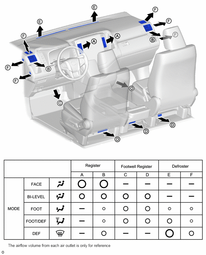
Air Outlets and Airflow Volume (Models without Rear Footwell Duct)
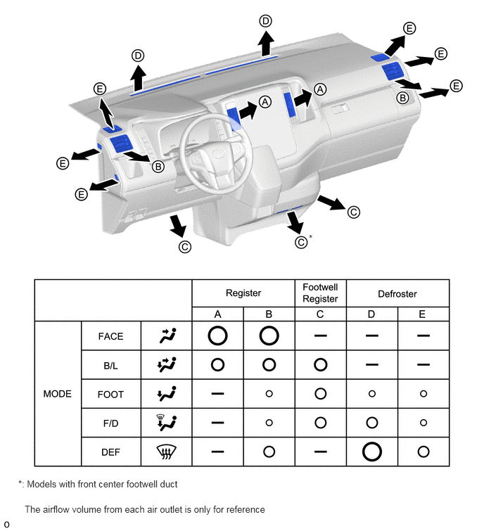
Air Outlets and Airflow Volume (Models with Rear Footwell Duct)