EXTERIOR PANELS / TRIM BODY STRUCTURE DETAILS BODY SHELL
CONSTRUCTION
Body Shell
The position of the body's structural parts is optimized, optimized connection methods are used and reinforcing materials are provided, creating a lightweight body structure with high rigidity and ensuring driving stability.
Each pillar is connected to the under body frameworks and a ring-shaped framework structure is used. As a result, the body shell has a high level of connecting rigidity and superior driving stability is provided.
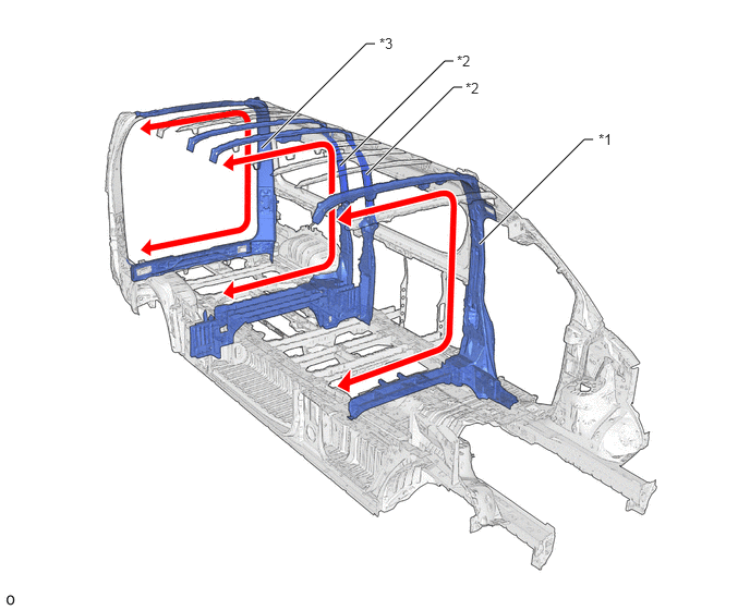
| *1 | Center Body Pillar | *2 | Quarter Body Pillar |
| *3 | Rear Body Pillar | - | - |
The dash panel sub-assembly (*2 in illustration) and front suspension tower (*1 in illustration) are directly connected, creating a highly rigid front suspension tower. Furthermore, a structure that connects the cowl assembly (*3 in illustration) and front suspension tower (*1 in illustration) is used, providing superior driving stability.
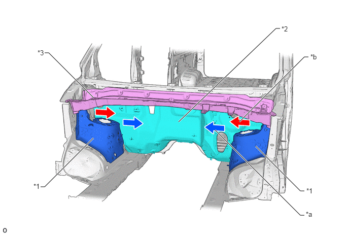
| *1 | Front Suspension Tower | *2 | Dash Panel Sub-assembly |
| *3 | Cowl Assembly | - | - |
| *a | Dash panel sub-assembly used as shared panel | *b | Cowl assembly used to increase lateral strength |
Design surface variations are emphasized and rigid reinforcements are positioned, reducing design surface panel thickness and weight. Consideration has been given to thin panels that do not easily deform or bend when pressed or heated.
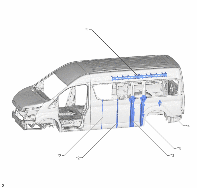
| *1 | Quarter Panel Extension Reinforcement LH | *2 | Roof Side Reinforcement Inner Rear |
| *3 | Quarter Lock Pillar LH | *4 | Quarter Panel Reinforcement LH |
Suspension Member
Frameworks are efficiently positioned near the load points of the front suspension, improving the rigidity at the load points of the front suspension. As a result, superior driving stability, ride comfort and NVH* performance are provided.
- HINT:
-
*: An abbreviation created by taking the first letter of Noise (unpleasant sounds and loud sounds), Vibration (vibrations from the engine and tires) and Harshness (vibrations felt through the steering wheel, seats and floor according to height changes in the road surface, etc.). NVH is used to describe the level of riding comfort and sound quality actually experienced by passengers.
To efficiently receive large loads input to the front suspension arm sub-assembly lower No. 1 (*2 / *4 in illustration) from the tire, the front frame assembly (*3 in illustration) is positioned directly horizontal to the front suspension arm sub-assembly lower No. 1 (*2 / *4 in illustration), creating a highly rigid structure.
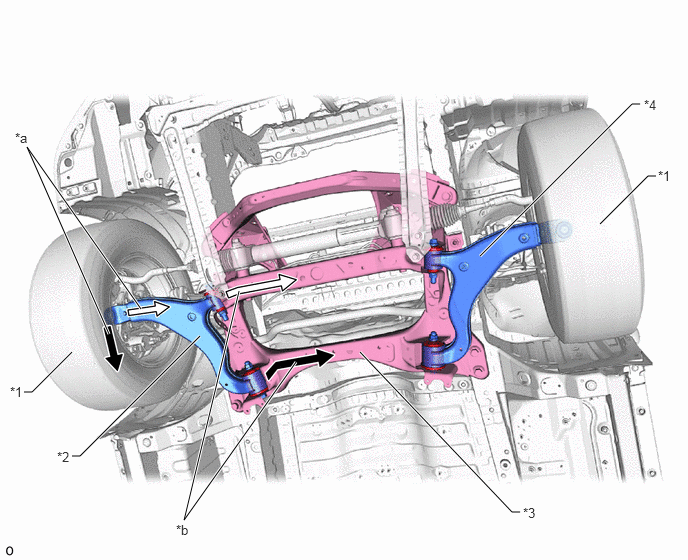
| *1 | Front Tire | *2 | Front Suspension Arm Sub-assembly Lower No. 1 RH |
| *3 | Front Frame Assembly | *4 | Front Suspension Arm Sub-assembly Lower No. 1 LH |
| *a | Load input to front suspension arm sub-assembly lower No. 1 RH from front tire | *b | Load input to front frame assembly from front suspension arm sub-assembly lower No. 1 RH |
Rear Suspension Installation Areas
Frameworks are efficiently positioned near the load points of the rear suspension, improving the rigidity at the load points of the rear suspension. As a result, superior driving stability, ride comfort and NVH performance are provided.
A structure where the rear shock absorber plate No. 1 (*2 in illustration) and rear floor No. 2 center member brace outer (*3 in illustration) are positioned on both sides of the rear side member (*4 in illustration) is used to suppress twisting deformation of the shock absorber rear (*1 in illustration) installation area in response to input from the shock absorber assembly rear (*1 in illustration), ensuring the rigidity of the load points.
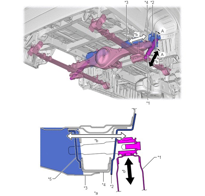
| *1 | Shock Absorber Assembly Rear RH | *2 | Rear Shock Absorber Plate No. 1 RH |
| *3 | Rear Floor No. 2 Center Member Brace Outer RH | *4 | Rear Side Member |
| *5 | Rear Shock Absorber Plate No. 2 RH | - | - |
| *a | A - A Cross Section | *b | Load input from shock absorber assembly rear (*1 in Illustration) |
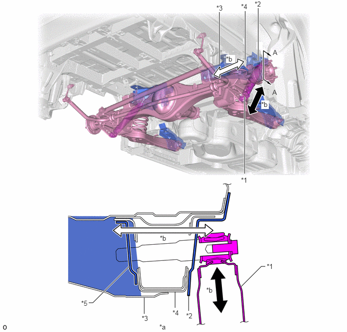
| *1 | Shock Absorber Assembly Rear RH | *2 | Rear Shock Absorber Plate No. 1 RH |
| *3 | Rear Floor No. 2 Center Member Brace Outer RH | *4 | Rear Side Member |
| *5 | Rear Shock Absorber Plate No. 2 RH | - | - |
| *a | A - A Cross Section | *b | Load input from shock absorber assembly rear (*1 in Illustration) |
Leaf Spring Front Side Installation Areas (Models with Leaf Spring Type Suspension System)
A hanger bracket structure (*4 in illustration), which is composed of 2 cross members (*2 in illustration) and outriggers (*3 in illustration), is used to handle the left and right loads (*a in illustration) input from the rear spring assembly (*1 in illustration), ensuring the rigidity of the load points of the leaf spring installation areas.
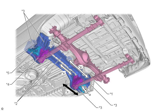
| *1 | Rear RH Spring Assembly | *2 | Cross Member |
| *3 | Outrigger | *4 | Hanger Bracket |
| *5 | Rear Suspension Member Brace RH | - | - |
| *a | Left and right loads input from rear RH spring assembly (*1 in Illustration) | - | - |
4-link Suspension Lower Control Arm and Upper Control Arm Installation Areas (Models with 4-link Type Suspension System)
Lower Control Arm
A rear spring hanger side plate No. 1 RH (*3 in illustration), which has many connections with other parts, is provided along the floor side member RH (*2 in illustration) to ensure the rigidity of the load points at the installation area of the lower control arm assembly RH (*1 in illustration) in response to front/rear input from the lower control arm assembly RH (*1 in illustration).
Upper Control Arm
An upper control link bracket sub-assembly RH (*7 in illustration), which connects the cross member (*5 in illustration) and rear side member (*6 in illustration), is provided to ensure the rigidity of the load points at the installation area of the upper control arm assembly (*4 in illustration) in response to front/rear input from the upper control arm assembly (*4 in illustration).
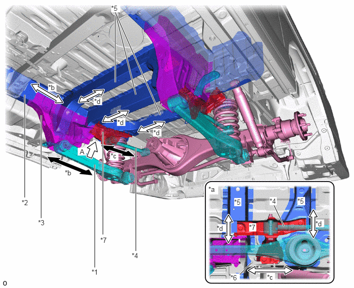
| *1 | Lower Control Arm Assembly RH | *2 | Floor Side Member RH |
| *3 | Rear Spring Hanger Side Plate No. 1 RH | *4 | Upper Control Arm Assembly |
| *5 | Cross Member | *6 | Rear Side Member |
| *7 | Upper Control Link Bracket Sub-assembly RH | - | - |
| *a | View from A | *b | Front/Rear input from lower control arm assembly RH (*1 in Illustration) |
| *c | Front/Rear input from upper control arm assembly (*4 in Illustration) | *d | Loads input from upper control arm assembly (*4 in Illustration) |
Leaf Spring Rear Side Installation Areas (Models with Leaf Spring Type Suspension System)
A rear floor side member plate (*5 in illustration), which reduces the offset from the rear side member (*6 in illustration), is provided to handle the left and right loads (*a in illustration) input to the spring shackle (*4 in illustration). Also, the shackle bracket (*2 in illustration) is composed of the rear spring hanger reinforcement FR (*1 in illustration), rear suspension arm bracket RR No. 2 (*8 in illustration) and rear floor side member plate (*5 in illustration), ensuring the rigidity of the load points of the spring shackle (*4 in illustration) installation areas.
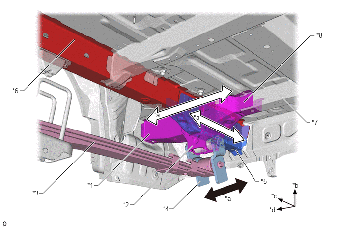
| *1 | Rear Spring Hanger Reinforcement FR RH | *2 | Shackle Bracket |
| *3 | Rear Spring Assembly | *4 | Spring Shackle |
| *5 | Rear Floor Side Member Plate RH | *6 | Rear Side Member RH |
| *7 | Rear Floor Cross Member No. 7 | *8 | Rear Suspension Arm Bracket RR RH No. 2 |
| *a | Left and right loads input to spring shackle (*4 in Illustration) | *b | Upside |
| *c | Front | *d | Right |
Rear Lateral Control Rod Installation Areas (Models with 4-link Type Suspension System)
The lateral rod support bracket FR (*4 in Illustration) and lateral rod support bracket RR (*5 in Illustration) are provided as a structure to connect the rear side member (*2 in Illustration) and rear floor cross member No. 6 (*3 in Illustration) to ensure the rigidity of the load points at the installation are of the rear lateral control rod assembly (*1 in Illustration) in response to left/right input from the rear lateral control rod assembly (*1 in Illustration).
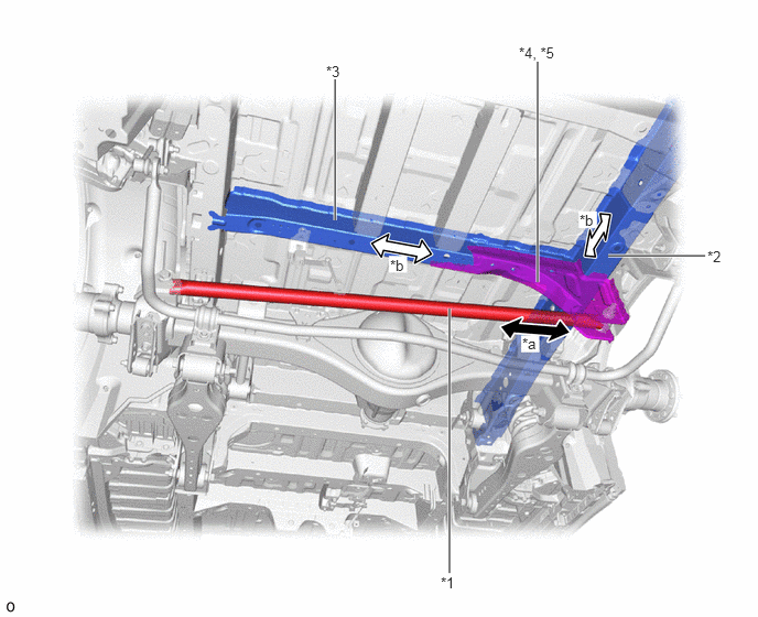
| *1 | Rear Lateral Control Rod Assembly | *2 | Rear Side Member |
| *3 | Rear Floor Cross Member No. 6 | *4 | Lateral Rod Support Bracket FR |
| *5 | Lateral Rod Support Bracket RR | - | - |
| *a | Left/Right input from rear lateral control rod assembly (*1 in Illustration) | *b | Loads input from rear lateral control rod assembly (*1 in Illustration) |
Straight Ladder Structure
A straight ladder structure that passes through the floor side members from the rear portion of the dash panel to the rear portion of the rear wheel house is used to ensure torsional rigidity of the floor.
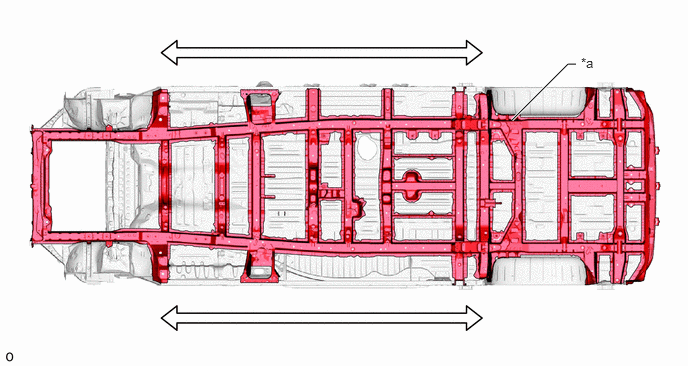
| *a | Straight Ladder Structure | - | - |
Spot Welding
An increased number of spot welding points are provided throughout the body, increasing the connectivity of the panels and providing superior driving stability (steering response and hand feedback).
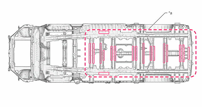
| *a | Increased Number of Spot Welding Points | - | - |
Rear Driving Stability Brace
Driving stability braces are provided near the rear suspension member installation areas to suppress body deformation, ensuring a superior feeling of grip.
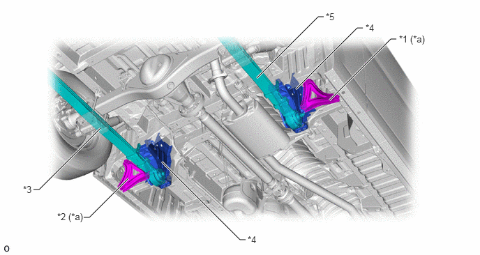
| *1 | Rear Suspension Member Brace RH | *2 | Rear Suspension Member Brace LH |
| *3 | Rear LH Spring Assembly | *4 | Rear Suspension Member |
| *5 | Rear RH Spring Assembly | - | - |
| *a | Driving Stability Brace | - | - |
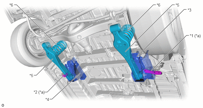
| *1 | Rear Suspension Member Brace RH | *2 | Rear Suspension Member Brace LH |
| *3 | Rear Spring Hanger FR RH | *4 | Rear Spring Hanger FR LH |
| *5 | Lower Control Arm Assembly | *6 | Coil Spring Rear |
| *a | Driving Stability Brace | - | - |
Driving Stability Braces Near Engine Compartment
Driving stability braces are provided near the engine compartment to efficiently strengthen rigidity, achieving superior steering response.
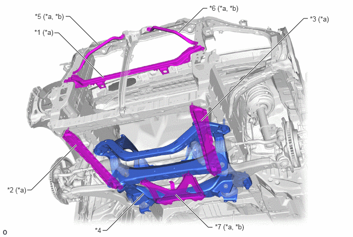
| *1 | Cooler Bracket | *2 | Side Rail Reinforcement Sub-assembly Rear RH |
| *3 | Side Rail Reinforcement Sub-assembly Rear LH | *4 | Front Frame Assembly |
| *5 | Radiator Support Brace Upper RH | *6 | Radiator Support Brace Upper LH |
| *7 | Front Suspension Brace Lower Center | - | - |
| *a | Driving Stability Brace | *b | VX Grade Only |
Structural Adhesive
Panel connections are strengthened to enhance body torsional rigidity, ensuring superior driving stability. In addition to spot welding, structural adhesive* is used for each door opening. Panel connections are strengthened to enhance body torsional rigidity, providing superior driving stability.
- HINT:
-
*: A Compared to conventional spot welding where panels are only connected at certain points, this adhesive is used together with welds to connect body surfaces, minimizing bending and warping to maximize rigidity.
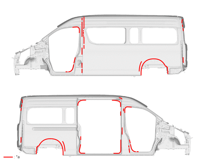
| *a | Structural Adhesive | - | - |