NAVIGATION / MULTI INFO DISPLAY NAVIGATION SYSTEM / MULTI INFORMATION SYSTEM CONTROL AUDIO CONTROL
FUNCTION OF MAIN COMPONENTS
| Component | Function | |
|---|---|---|
|
*1: Except models with 12 speakers *2: Models with 12 speakers *3: Models with telematics system *4: Models without telematics system *5: Models with Wi-Fi communication function *6: Models with DAB tuner *7: Models with automatic transmission *8: Models with manual transmission |
||
| Audio Head Unit (Radio and Display Receiver Assembly) | ·
Outputs the audio signal of the selected audio source to the speakers*1 or stereo component amplifier assembly*2. ·
Sends each sound source and hands-free system status to the combination meter. ·
Receives navigation information, etc. image and audio signals and operation status via direct line from the navigation ECU or USB communication. ·
Based on the image signal sent from the navigation ECU, displays the map screen, operation screen, etc. ·
Sends the operation signals input via the capacitive touch display panel to the navigation ECU. ·
Receives audio signals such as voice guidance from the navigation ECU and sends them to the speakers. ·
Sends a startup signal to the navigation ECU when the audio system started. ·
Sends microphone voice signals sent from the DCM to the navigation ECU.*3 ·
Sends microphone voice signals to the navigation ECU.*4 ·
Sends an R shift position signal to the navigation ECU. ·
Using the equipped 2.4GHz frequency band wireless LAN, communicates via Wi-Fi with a wireless LAN access point, a tethering capable mobile phone or Wi-Fi mobile router.*5 |
|
| Major Components of Radio and Display Receiver Assembly | Multi-display Panel | ·
Displays a map screen or an operation screen based on image signals from the navigation ECU. ·
Sends operation signals input via the capacitive display panel to the navigation ECU. |
| Navigation ECU | ·
Contains the navigation ECU, gyro sensor, GPS signal receiver and storage device, manages the radio and operation signals received from the audio head unit, and controls the navigation system. ·
Sends navigation information, etc. image and sound signals and the operation status to the audio head unit. |
|
| Major Components of Navigation ECU | Navigation Computer | ·
Corrects the vehicle location based on location information calculated from the GPS information, vehicle speed signal, information from equipped sensors and the shift status. ·
Using the calculated vehicle location mark and map database, sends the information and operation status to the audio head unit. ·
Sends the audio signals such as voice guidance provided based on the vehicle location to the audio head unit. ·
Sends the voice guidance audio signal to the audio head unit. ·
Sends navigation information such as the vehicle direction and route guidance, etc. to the combination meter assembly via the audio head unit. |
| Gyro Sensor | Detects the vehicle rotational speed around the vertical axis (yaw moments) and sends it to the navigation ECU. | |
| GPS Receiver | Demodulates the GPS information received by the telephone and GPS antenna (for front side), calculates the vehicle position and sends the position signal to the navigation ECU. | |
| Storage Device | Stores map data and the navigation system control program. | |
| Speakers | Output the audio sounds. | |
| Navigation Antenna Assembly
·
GPS Antenna |
Receives GPS signals from satellites in orbit around the Earth, at an altitude of approximately 20,200 km (12,600 miles), and sends them to the navigation ECU. | |
| Roof Antenna Pole Sub-assembly
·
AM ·
FM |
Receives radio broadcasting signals (AM/FM). | |
| No. 1 Amplifier Antenna Assembly | Amplifies radio broadcasting signals from the radio antenna and sends them to the audio head unit. | |
| Windshield Glass Print Antenna*6
·
DAB |
Receives radio broadcasting signals (DAB). | |
| Digital Audio Broadcasting Antenna Assembly*6 | Amplifies DAB signals from the DAB antenna and sends them to the audio head unit. | |
| Parking Brake Switch Assembly | Distributes signals from the GPS antenna to the audio head unit. | |
| Park/Neutral Position Switch Assembly*7 | Sends a shift position R signal to the audio head unit. | |
| Back-up Light Switch Assembly*8 | ||
| Steering Pad Switch Assembly | Sends operation signals such as volume adjustment, mode selection and song selections to the audio head unit. | |
| Telephone Microphone Assembly*4 | ·
Receives the user's voice through the microphone module. ·
Recognizes speech during voice recognition system operation and sends the audio signal to the DCM. |
|
| Communication Telematics Box*3 | ·
Receives the user's voice through the microphone module. ·
Recognizes speech during voice recognition system operation and sends the audio signal to the audio head unit. |
|
| No. 1 Stereo Jack Adapter Assembly | ·
Sends audio signals to the audio head unit when an auxiliary device is connected. ·
Communicates with the audio head unit via a USB communication line when a USB memory device, portable audio player (USB type) or Apple product is connected. |
|
| Stereo Component Amplifier Assembly*2 | Amplifies audio signals sent from the audio head unit and sends them to the speakers and DCM*3. | |
| DCM (Telephone Transceiver Assembly)*3 | Sends microphone voice signals sent from the telephone microphone assembly to the audio head unit. | |
| Combination Meter Assembly | ·
Sends vehicle speed signals to the audio head unit, DCM, Navigation ECU and stereo component amplifier assembly*2. ·
Displays the status information of each audio source, hands-free system and voice recognition system which is received from the audio head unit on the multi-information display. ·
Sends operation signals to the audio head unit when the audio source and hands-free system settings are set on the multi-information display. |
|
FUNCTION
When guidance is being performed, traffic information and route information such as distance to the destination, traveling time, etc. are displayed on the map screen route guidance bar.
When the amount of fuel is low, a warning message is displayed and nearby gas stations are displayed on the multi-display. The user can set a nearby gas station as a destination by selecting from a list of nearby gas stations.
When route guidance is being performed and an alternative route is driven, the alternative route is memorized. When an alternative route other than the suggested route was chosen, the navigation system learns the route after it has been driven multiple times and displays it as a suitable route search result.
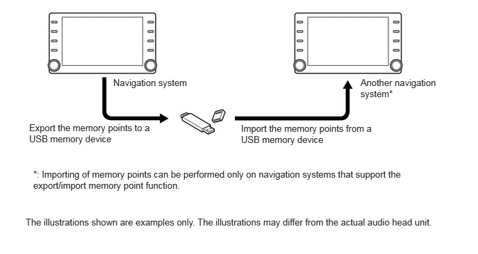
Memory Points Export/Import Function (Models with Memory Points Export/Import Function)
The navigation system supports functions to export/import memory points. This function allows memory points stored in the audio head unit to be transferred to another navigation system (such as another audio head unit, etc.) via USB.
Memory points export/import procedure
DIAGNOSIS
For details on the procedure required to enter the Service Menu screen, refer to the Repair Manual.