BRAKE SYSTEM (OTHER) VACUUM PUMP(for 7GR-FKS) ON-VEHICLE INSPECTION
PROCEDURE

 85110
1.REMOVE WINDSHIELD WIPER MOTOR ASSEMBLY
47220D
2.DISCONNECT BRAKE MASTER CYLINDER RESERVOIR ASSEMBLY
55738D
3.REMOVE NO. 2 HEATER AIR DUCT SPLASH SHIELD SEAL
55701J
4.REMOVE OUTER COWL TOP PANEL SUB-ASSEMBLY
5. OPERATION CHECK
Slide the clip and disconnect the union to connector tube hose from the vacuum pump assembly.
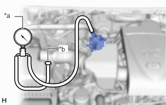
| *a | Vacuum Gauge |
| *b | Plug |
Connect the hose of the vacuum gauge to the vacuum pump assembly.
Start the engine and warm it up for more than 2 minutes.
With the engine idling, check the vacuum of the vacuum pump assembly.
- Standard Pressure:
More than 86.7 kPa (650 mmHg, 25.6 in.Hg)
If the pressure is less than the standard, disassemble and inspect the vacuum pump. If necessary, replace the vacuum pump assembly.
Click hereBrake>BRAKE SYSTEM (OTHER)>VACUUM PUMP (for 7GR-FKS)>INSPECTION
- HINT:
-
Always perform this operation check procedure after replacing or servicing the vacuum pump assembly.
Remove the vacuum gauge from the vacuum pump assembly.
Connect the union to connector tube hose to the vacuum pump assembly, and slide the clip to secure it.
55701J
6.INSTALL OUTER COWL TOP PANEL SUB-ASSEMBLY
55738D
7.INSTALL NO. 2 HEATER AIR DUCT SPLASH SHIELD SEAL
47220D
8.CONNECT BRAKE MASTER CYLINDER RESERVOIR ASSEMBLY
85110
9.INSTALL WINDSHIELD WIPER MOTOR ASSEMBLY