BRAKE SYSTEM (OTHER) VACUUM PUMP(for 1GD-FTV) REMOVAL
CAUTION / NOTICE / HINT
The necessary procedures (adjustment, calibration, initialization, or registration) that must be performed after parts are removed, installed, or replaced during the vacuum pump assembly removal/installation are shown below.
| Replacement Part or Procedure | Necessary Procedures | Effect/Inoperative Function When Necessary Procedures are not Performed | Link |
|---|---|---|---|
| Disconnect cable from negative (-) battery terminal | Memorize steering angle neutral point | Parking assist monitor system | ( ) |
- HINT:
-
When the cable is disconnected / reconnected to the battery terminal, systems temporarily stop operating. However, each system has a function that completes learning the first time the system is used.
- ·
Learning completes when vehicle is driven
Effect/Inoperative Function When Necessary Procedures are not Performed Necessary Procedures Link Stop and start system Drive the vehicle until stop and start control is permitted (approximately 5 to 60 minutes). ( )
Lane control system Drive the vehicle straight ahead at 15 km/h (10 mph) or more for 1 second or more. ( )
Pre-collision system
·Learning completes when vehicle is operated normally
Effect/Inoperative Function When Necessary Procedures are not Performed Necessary Procedures Link Power slide door system Fully close the slide door by hand.
- HINT:
-
Initialization is not necessary if the above procedures are performed while the slide door is closed.
( )
Air conditioning system After the ignition switch is turned to ON, the servo motor standard position is recognized. -
PROCEDURE

 1. PRECAUTION
- NOTICE:
-
After turning the ignition switch off, waiting time may be required before disconnecting the cable from the negative (-) battery terminal.
-
Click hereGeneral>SETUP>WHEN DISCONNECTING OR RECONNECTING BATTERY TERMINAL>BEFORE DISCONNECTING BATTERY
11201
2.REMOVE CYLINDER HEAD COVER SUB-ASSEMBLY
w/ EGR Cooler:
Click hereEngine / Hybrid System>1GD-FTV (ENGINE MECHANICAL)>CAMSHAFT (w/ EGR Cooler)>REMOVAL
w/o EGR Cooler
Click hereEngine / Hybrid System>1GD-FTV (ENGINE MECHANICAL)>CAMSHAFT (w/o EGR Cooler)>REMOVAL
3.REMOVE NO. 3 CAMSHAFT BEARING CAP
w/ EGR Cooler:
Click hereEngine / Hybrid System>1GD-FTV (ENGINE MECHANICAL)>CAMSHAFT (w/ EGR Cooler)>REMOVAL
w/o EGR Cooler
Click hereEngine / Hybrid System>1GD-FTV (ENGINE MECHANICAL)>CAMSHAFT (w/o EGR Cooler)>REMOVAL
44773F
4.DISCONNECT UNION TO CONNECTOR TUBE HOSE
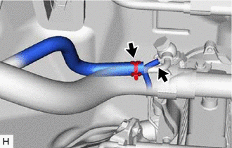
Slide the clip and disconnect the union to connector tube hose from the vacuum pump assembly.
Disconnect the No. 1 vacuum transmitting hose from the vacuum pump assembly.
29300
5.REMOVE VACUUM PUMP ASSEMBLY
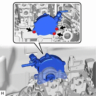
Remove the 3 bolts from the vacuum pump.
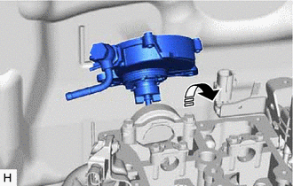
Tilt and pull the vacuum pump upwards toward the rear while avoiding the dash panel to remove the vacuum pump.
- NOTICE:
-
Do not damage the camshaft and vacuum pump shaft.
Remove the No. 2 O-ring and No. 3 O-ring from the vacuum pump assembly.
11382C
6.REMOVE CAMSHAFT OIL SEAL RETAINER
Remove the camshaft oil seal retainer from the vacuum pump assembly.
29300F
7.REMOVE UNION
Fix the vacuum pump in a vise between aluminum plates.
- NOTICE:
-
Place aluminum plates on the vise to prevent damage to the pump.
Remove the union bolt, union and 2 gaskets.