RC60J MANUAL TRANSMISSION / TRANSAXLE INPUT SHAFT REASSEMBLY
PROCEDURE

 33311A
1.INSTALL FRONT INPUT SHAFT BEARING
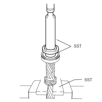
Using SST and a press, install a new front input shaft bearing to the input shaft.
- SST
- 09316-60012 (09316-00011, 09316-00061)
09527-20011
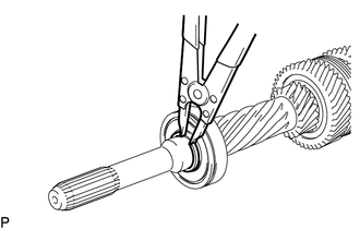
Select a new snap ring that will allow minimal axial play.
- Standard Clearance:
0.1 mm (0.00394 in.) or less
- Standard Snap Ring:
Part No. Mark Thickness 90520-T0142 A 2.65 to 2.70 mm (0.1044 to 0.1062 in.) 90520-T0143 B 2.70 to 2.75 mm (0.1063 to 0.1082 in.) 90520-T0144 C 2.75 to 2.80 mm (0.1083 to 0.1102 in.) 90520-T0145 D 2.80 to 2.85 mm (0.1103 to 0.1122 in.) 90520-T0146 E 2.85 to 2.90 mm (0.1122 to 0.1141 in.) 90520-T0147 F 2.90 to 2.95 mm (0.1142 to 0.1161 in.)
Using a snap ring expander, install the snap ring to the input shaft.
2.INSTALL 5TH GEAR NEEDLE ROLLER BEARING
- NOTICE:
-
Although either type may be installed, make sure to follow the installation procedure for each type.
for Split Type:
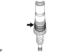
Coat the 5th gear needle roller bearing with gear oil and install it to the input shaft.
for Integrated Type:
Coat the 5th gear needle roller bearing with gear oil and install it to the input shaft.
- NOTICE:
-
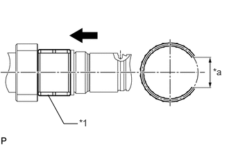 0.719,1.427 0.958,1.865 0.958,1.865 1.167,1.865 false 1.188,1.771 1.479,2 0.292,0.229 10 false *1 3.198,1 3.406,1.229 0.208,0.229 10 false *a
*1 5th Gear Needle Roller Bearing *a Do not expand the 5th gear needle roller bearing 22 mm (0.866 in.) or more. 
Install in this Direction
- ·
Install the 5th gear needle roller bearing in the axial direction of the input shaft.
·Do not expand the 5th gear needle roller bearing 22 mm (0.866 in.) or more.
33336
3.INSTALL 5TH GEAR
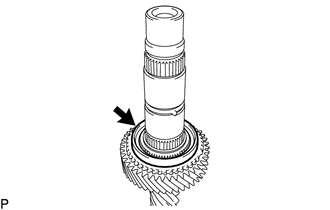
Coat the 5th gear with gear oil and install it to the input shaft.
33369
4.INSTALL NO. 3 SYNCHRONIZER RING
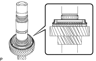
Coat the No. 3 synchronizer ring with gear oil, and then install it to the input shaft.
33393
5.INSTALL NO. 3 TRANSMISSION CLUTCH HUB
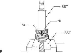
| *a | Protrusion of the No. 3 Synchronizer Ring |
| *b | Groove of the No. 3 Transmission Clutch Hub |
Using SST and press, install the No. 3 transmission clutch hub to the input shaft.
- SST
- 09308-14010
09527-21011
- NOTICE:
-
Align the protrusion of the No. 3 synchronizer ring with the groove of the No. 3 transmission clutch hub as shown in the illustration
33321D
6.INSTALL CLUTCH HUB SET SHAFT SNAP RING
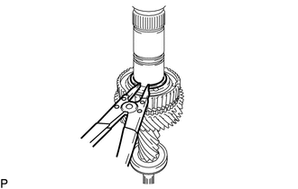
Select a new clutch hub set shaft snap ring that will allow minimal axial play.
- Standard Clearance:
0.1 mm (0.00394 in.) or less
- Standard Snap Ring:
Part No. Mark Thickness 90520-T0148 A 1.80 to 1.85 mm (0.0709 to 0.0728 in.) 90520-T0149 B 1.85 to 1.90 mm (0.0729 to 0.0748 in.) 90520-T0150 C 1.90 to 1.95 mm (0.0749 to 0.0767 in.) 90520-T0151 D 1.95 to 2.00 mm (0.0768 to 0.0787 in.) 90520-T0152 E 2.00 to 2.05 mm (0.0788 to 0.0807 in.) 90520-T0153 F 2.05 to 2.10 mm (0.0808 to 0.0826 in.)
Using a snap ring expander, install the clutch hub set shaft snap ring to the input shaft.
33365
7.INSTALL NO. 1 SYNCHROMESH SHIFTING KEY
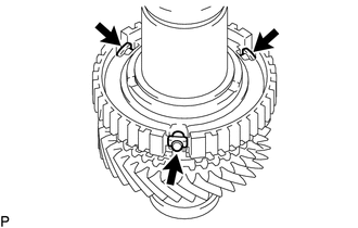
Install the 3 No. 1 synchromesh shifting keys to the No. 3 transmission clutch hub.
33364
8.INSTALL NO. 2 TRANSMISSION HUB SLEEVE
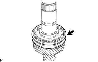
Apply a light coat of gear oil to the sleeve and hub.
Install the No. 2 transmission hub sleeve to the No. 3 transmission clutch hub.
33337B
9.INSTALL 6TH GEAR SPACER
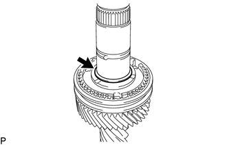
Coat the 6th gear spacer with gear oil, and then install it to the input shaft.
33337A
10.INSTALL 6TH GEAR NEEDLE ROLLER BEARING
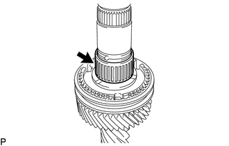
Coat the 6th gear needle roller bearing with gear oil, and then install it to the input shaft.
33369
11.INSTALL NO. 3 SYNCHRONIZER RING
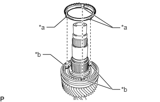
| *a | Protrusion |
| *b | Groove |
Coat the No. 3 synchronizer ring with gear oil, and then install it to the No. 3 transmission clutch hub.
- NOTICE:
-
Align the protrusion of the No. 3 synchronizer ring with the groove of the No. 3 transmission clutch hub.
33337
12.INSTALL 6TH GEAR SUB-ASSEMBLY
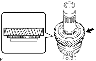
Coat the 6th gear sub-assembly with gear oil, and then install it to the input shaft.
- HINT:
-
Make sure that the 6th gear sub-assembly faces the correct direction as shown in the illustration.
Check that the 6th gear sub-assembly and No. 3 synchronizer ring move smoothly.
33342A
13.INSTALL GEAR THRUST WASHER STRAIGHT PIN
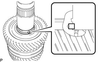
Install the gear thrust washer straight pin to the input shaft.
33342C
14.INSTALL 3RD GEAR THRUST WASHER
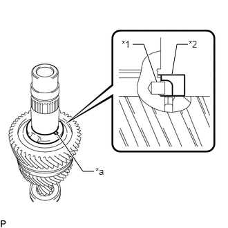
| *1 | Gear Thrust Washer Straight Pin |
| *2 | 3rd Gear Thrust Washer |
| *a | Groove |
Coat the 3rd gear thrust washer with gear oil and install it to the input shaft.
- HINT:
-
Align the groove of the 3rd gear thrust washer with the gear thrust washer straight pin.
33342B
15.INSTALL GEAR THRUST WASHER SHAFT SNAP RING
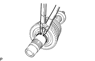
Select a new gear thrust washer shaft snap ring that will allow minimal axial play.
- Standard Clearance:
0.1 mm (0.00394 in.) or less
- Standard Snap Ring:
Part No. Mark Thickness 90520-T0155 A 2.07 to 2.12 mm (0.0815 to 0.0834 in.) 90520-T0156 B 2.12 to 2.17 mm (0.0835 to 0.0854 in.) 90520-T0157 C 2.17 to 2.22 mm (0.0855 to 0.0874 in.) 90520-T0158 D 2.22 to 2.27 mm (0.0875 to 0.0893 in.) 90520-T0159 E 2.27 to 2.32 mm (0.0894 to 0.0913 in.) 90520-T0160 F 2.32 to 2.37 mm (0.0914 to 0.0933 in.)
Using a snap ring expander, install the gear thrust washer shaft snap ring to the input shaft.
33333D
16.INSTALL 3RD GEAR SPACER
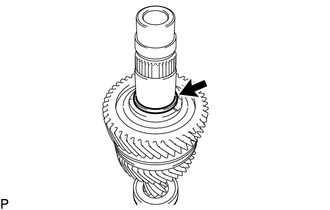
Coat the 3rd gear spacer with gear oil and install it to the input shaft.
33333A
17.INSTALL 3RD GEAR NEEDLE ROLLER BEARING
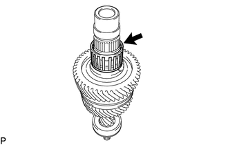
Coat the 3rd gear needle roller bearing with gear oil, and then install it to the input shaft.
33333
18.INSTALL 3RD GEAR
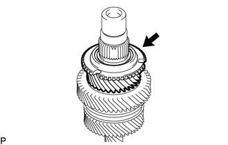
Coat the 3rd gear with gear oil, and then install it to the input shaft.
33039
19.INSTALL NO. 3 SYNCHRONIZER RING SET
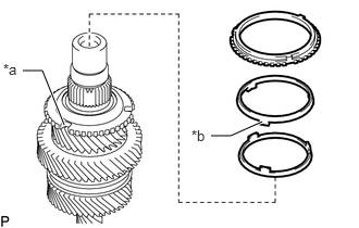
| *a | Groove |
| *b | Protrusion |
Coat the No. 3 synchronizer ring set with gear oil, and then install it to the input shaft.
- NOTICE:
-
Align the protrusion of the No. 3 synchronizer ring set with the groove of the 3rd gear.
33362
20.INSTALL NO. 2 TRANSMISSION CLUTCH HUB
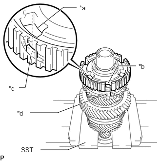
| *a | Hole of the No. 2 Transmission Clutch Hub |
| *b | Groove of the No. 2 Transmission Clutch Hub |
| *c | Protrusion of the No. 3 Synchronizer Ring (inner ring) |
| *d | Protrusion of the No. 3 Synchronizer Ring |
Using SST, set the input shaft
- SST
- 09527-20011
Temporarily install the No. 2 transmission clutch hub to the input shaft.
- HINT:
- ·
Align the protrusion of the No. 3 synchronizer ring set (inner ring) with the hole of the No. 2 transmission clutch hub as shown in the illustration
·Align the protrusion of the No. 3 synchronizer ring set with the groove of the No. 2 transmission clutch hub as shown in the illustration
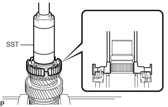
Using SST and a press, install the No. 2 transmission clutch hub to the input shaft.
- SST
- 09527-20011
09309-37010
33365
21.INSTALL NO. 1 SYNCHROMESH SHIFTING KEY
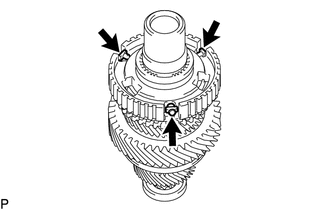
Install the 3 No. 1 synchromesh shifting keys to the No. 2 transmission clutch hub.
33364
22.INSTALL NO. 2 TRANSMISSION HUB SLEEVE
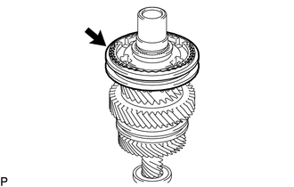
Apply a light coat of gear oil to the sleeve and hub.
Install the No. 2 transmission hub sleeve to the No. 2 transmission clutch hub.
33362A
23.INSTALL NO. 2 CLUTCH HUB SETTING SHAFT SNAP RING
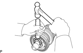
Select a new No. 2 clutch hub setting shaft snap ring that will allow minimal axial play.
- Standard Clearance:
0.1 mm (0.00394 in.) or less
- Standard Snap Ring:
Part No. Mark Thickness 90520-T0161 A 2.50 to 2.55 mm (0.0983 to 0.1004 in.) 90520-T0162 B 2.55 to 2.60 mm (0.1004 to 0.1023 in.) 90520-T0163 C 2.60 to 2.65 mm (0.1024 to 0.1043 in.) 90520-T0164 D 2.65 to 2.70 mm (0.1044 to 0.1062 in.) 90520-T0165 E 2.70 to 2.75 mm (0.1063 to 0.1082 in.) 90520-T0166 F 2.75 to 2.80 mm (0.1083 to 0.1102 in.)
Using a brass bar and hammer, install the No. 2 clutch hub setting shaft snap ring to the input shaft.
33333
24.INSPECT 3RD GEAR THRUST CLEARANCE
33333
25.INSPECT 3RD GEAR RADIAL CLEARANCE
33337
26.INSPECT 6TH GEAR SUB-ASSEMBLY THRUST CLEARANCE
33337
27.INSPECT 6TH GEAR SUB-ASSEMBLY RADIAL CLEARANCE
33336
28.INSPECT 5TH GEAR THRUST CLEARANCE
33336
29.INSPECT 5TH GEAR RADIAL CLEARANCE