1GD-FTV EMISSION CONTROL UREA INJECTOR INSTALLATION
PROCEDURE

 23203A
1.INSTALL UREA INJECTOR SET
Clean the surfaces of the urea injector set and front exhaust pipe assembly.
- NOTICE:
-
Clean off any white sealant that is present on the installation surface of the urea injector set.
Install a new gasket and the urea injector set to the front exhaust pipe assembly with 2 new nuts.
- Torque:
- 30 N*m (306 kgf*cm, 22 ft.*lbf)
Connect the connector to the urea injector set.
77840A
2.CONNECT UREA TUBE WITH HEATER ASSEMBLY
- NOTICE:
- ·
Check for dirt or mud on the urea injector set and around the urea tube with heater connector before connection. Clean if necessary.
·In order to prevent the urea injector set interior set portion from drying, perform installation and removal work as quickly as possible.
Connect the urea tube with heater assembly to the urea injector set.
- HINT:
-
If there is any solidified urea solution (white solids) on the connection areas of the urea tube with heater assembly and urea injector set, clean the solids off with water. Otherwise, they may prevent the O-ring from sealing properly.
Wash the connection area of the urea tube with heater connector with water to remove all solidified urea solution (white solids).
Wipe off the connection area of the urea injector set with water to remove all solidified urea solution (white solids).
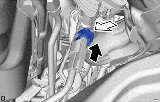
Align the axis of the connector with the axis of the urea injector set. Push the urea tube with heater connector into the urea injector set until the urea tube with heater connector makes a "click" sound.
After connecting the urea injector set and the urea tube with heater connector, check that the urea injector set and urea tube with heater connector are securely connected by trying to pull them apart.
Attach the lock claws to the urea tube connector by pushing down on the cover.
51408B
3.INSTALL ENGINE UNDER COVER SUB-ASSEMBLY RH (w/ Cover)
51405A
4.INSTALL NO. 1 ENGINE UNDER COVER SUB-ASSEMBLY
52618
5.INSTALL LOWER FRONT BUMPER ABSORBER
51406A
6.INSTALL NO. 2 ENGINE UNDER COVER SUB-ASSEMBLY (w/ No. 2 Engine Under Cover Sub-assembly)