1GD-FTV ENGINE MECHANICAL CYLINDER HEAD REASSEMBLY
PROCEDURE

 1.INSTALL STUD BOLT
- NOTICE:
-
If a stud bolt is deformed or the threads are damaged, replace it.
Using an E6 "TORX" socket wrench, install the stud bolts labeled A to the cylinder head sub-assembly.
- Torque:
- for stud bolt A : 6.0 N*m (61 kgf*cm, 53 in.*lbf)
Install the stud bolts labeled B to the cylinder head sub-assembly.
- Torque:
- for stud bolt B : 10 N*m (102 kgf*cm, 7 ft.*lbf)
Using an E10 "TORX" socket wrench, install the stud bolts labeled C and D to the cylinder head sub-assembly.
- Torque:
- for stud bolt C : 19 N*m (194 kgf*cm, 14 ft.*lbf)
- for stud bolt D : 20 N*m (204 kgf*cm, 15 ft.*lbf)
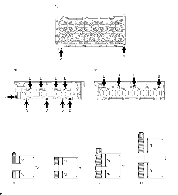
| *a | Cylinder Head Cover Sub-assembly Side | *b | Exhaust Manifold Side |
| *c | Intake Manifold Side | *d | 12 mm (0.472 in.) |
| *e | 37 mm (1.46 in.) | *f | 34 mm (1.34 in.) |
| *g | 23 mm (0.906 in.) | *h | 15 mm (0.591 in.) |
| *i | 25 mm (0.984 in.) | *j | 65 mm (2.56 in.) |
| *k | 40 mm (1.57 in.) | - | - |
11117E
2.INSTALL NO. 1 STRAIGHT SCREW PLUG WITH HEAD
Using a 6 mm hexagon wrench, install 4 new No. 1 straight screw plug with heads to the cylinder head sub-assembly.
- Torque:
- 25 N*m (255 kgf*cm, 18 ft.*lbf)
13711E
3.INSTALL VALVE STEM OIL SEAL
Apply a light coat of engine oil to new valve stem oil seals.
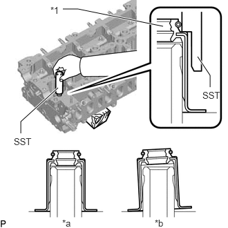
| *1 | Valve Stem Oil Seal |
| *a | CORRECT |
| *b | INCORRECT |
Using SST, push in the intake valve stem oil seals and exhaust valve stem oil seals to the valve guide bush.
- SST
- 09201-41020
- NOTICE:
-
Failure to use SST will cause the valve stem oil seal to be damaged or improperly seated.
13711
4.INSTALL INTAKE VALVE
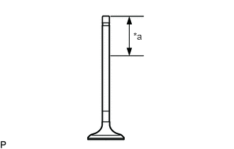
| *a | 30 mm (1.18 in.) or more |
Apply plenty of engine oil to the tip area of the intake valve shown in the illustration.
Install the intake valve, valve compression spring and valve spring retainer to the cylinder head sub-assembly.
- NOTICE:
-
Install the same parts in the same combination to their original locations.
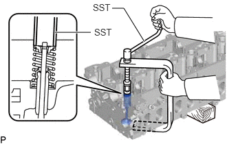
Using SST and wooden blocks, compress the valve compression spring and install the valve spring retainer locks to the valve spring retainer.
- SST
- 09202-70020
09202-00021
Using a plastic-faced hammer, lightly tap the intake valve stem tip to ensure a proper fit.
- NOTICE:
-
Be careful not to damage the valve spring retainer.
13715
5.INSTALL EXHAUST VALVE
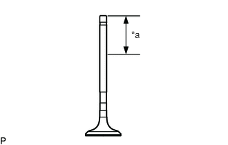
| *a | 30 mm (1.18 in.) or more |
Apply plenty of engine oil to the tip area of the exhaust valve shown in the illustration.
Install the exhaust valve, valve compression spring and valve spring retainer to the cylinder head sub-assembly.
- NOTICE:
-
Install the same parts in the same combination to their original locations.
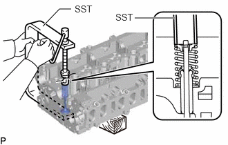
Using SST and wooden blocks, compress the valve compression spring and install the valve spring retainer locks to the valve spring retainer.
- SST
- 09202-70020
09202-00021
Using a plastic-faced hammer, lightly tap the exhaust valve stem tip to ensure a proper fit.
- NOTICE:
-
Be careful not to damage the valve spring retainer.
13716
6.INSTALL VALVE STEM CAP
Apply a light coat of engine oil to the valve stem caps.
Install the 16 valve stem caps to the cylinder head sub-assembly.
- NOTICE:
- ·
Install the valve stem cap at the same place it was removed from.
·Do not drop the valve stem caps into the cylinder head sub-assembly.