Home › Vehicle Interior › MIRROR (INT) › DIGITAL REAR-VIEW MIRROR SYSTEM
RM35X0E _58 Vehicle Interior _078376 MIRROR (INT) _0384903 DIGITAL REAR-VIEW MIRROR SYSTEM J

MIRROR (INT)  DIGITAL REAR-VIEW MIRROR SYSTEM  The Camera Malfunction Indicator Displays and the Screen is Darkened  


DESCRIPTION

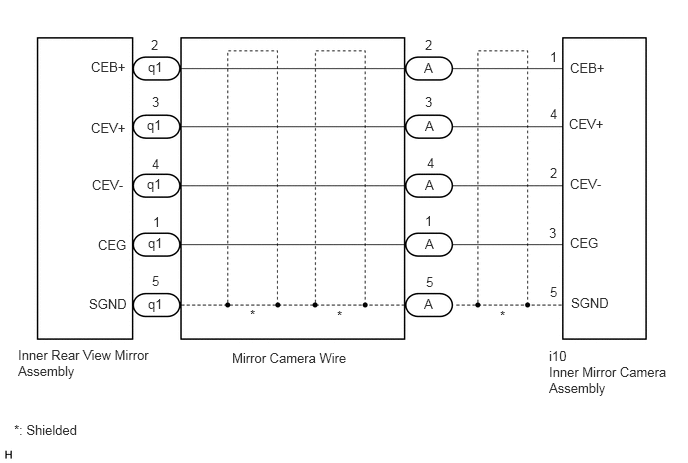
The image signals sent from the inner mirror camera assembly are input to the inner rear view mirror assembly via the vehicle wire harness and then displayed on the screen.

WIRING DIAGRAM

for Standard Roof:
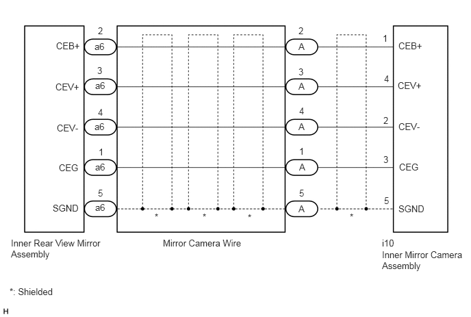

E416780E01
0.167,3.615 1.552,4.042 1.385,0.427 10 false Inner Rear View Mirror Assembly 1.438,0.625 1.75,0.823 0.313,0.198 10 false a6 1.448,1.219 1.76,1.417 0.313,0.198 10 false a6 1.438,1.844 1.75,2.042 0.313,0.198 10 false a6 1.448,2.458 1.76,2.656 0.313,0.198 10 false a6 1.448,3.073 1.76,3.271 0.313,0.198 10 false a6 2.479,3.615 3.74,3.865 1.26,0.25 10 false Mirror Camera Wire 5.813,3.615 6.271,3.813 0.458,0.198 10 false i10 5.813,3.792 7.031,4.26 1.219,0.469 10 false Inner Mirror Camera Assembly 0.146,4.354 0.927,4.563 0.781,0.208 10 false *: Shielded 2.354,3.219 2.51,3.417 0.156,0.198 10 false * 3.083,3.219 3.24,3.417 0.156,0.198 10 false * 3.771,3.229 3.99,3.385 0.219,0.156 10 false * 5.323,3.219 5.542,3.375 0.219,0.156 10 false * 0.854,0.615 1.469,0.813 0.615,0.198 10 false CEB+ 0.844,1.24 1.458,1.438 0.615,0.198 10 false CEV+ 0.865,1.865 1.479,2.063 0.615,0.198 10 false CEV- 0.896,2.469 1.354,2.667 0.458,0.198 10 false CEG 0.802,3.083 1.417,3.281 0.615,0.198 10 false SGND 6.063,3.094 6.677,3.292 0.615,0.198 10 false SGND 6.073,2.458 6.531,2.656 0.458,0.198 10 false CEG 6.063,1.844 6.677,2.042 0.615,0.198 10 false CEV- 6.052,1.219 6.667,1.417 0.615,0.198 10 false CEV+ 6.063,0.615 6.677,0.813 0.615,0.198 10 false CEB+ 1.49,0.385 1.646,0.583 0.156,0.198 10 false 2 1.479,0.99 1.635,1.188 0.156,0.198 10 false 3 1.49,1.625 1.646,1.823 0.156,0.198 10 false 4 1.5,2.229 1.656,2.427 0.156,0.198 10 false 1 1.49,2.854 1.646,3.052 0.156,0.198 10 false 5 4.542,0.625 5,0.823 0.458,0.198 10 false A 4.542,1.229 5,1.427 0.458,0.198 10 false A 4.542,1.844 5,2.042 0.458,0.198 10 false A 4.552,2.458 5.01,2.656 0.458,0.198 10 false A 4.542,3.094 5,3.292 0.458,0.198 10 false A 4.542,0.385 4.698,0.583 0.156,0.198 10 false 2 4.542,1.01 4.698,1.208 0.156,0.198 10 false 3 4.552,1.604 4.708,1.802 0.156,0.198 10 false 4 4.552,2.219 4.708,2.417 0.156,0.198 10 false 1 4.552,2.854 4.708,3.052 0.156,0.198 10 false 5 5.823,0.5 5.979,0.698 0.156,0.198 10 false 1 5.844,1.115 6,1.313 0.156,0.198 10 false 4 5.833,1.75 5.99,1.948 0.156,0.198 10 false 2 5.833,2.344 5.99,2.542 0.156,0.198 10 false 3 5.844,2.969 6,3.167 0.156,0.198 10 false 5


for High Roof:


E416241E01
0.188,3.615 1.563,3.99 1.375,0.375 10 false Inner Rear View Mirror Assembly 1.542,0.615 2,0.813 0.458,0.198 10 false q1 2.604,3.198 2.823,3.375 0.219,0.177 10 false * 5.719,3.625 6.177,3.823 0.458,0.198 10 false i10 5.719,3.792 6.958,4.167 1.24,0.375 10 false Inner Mirror Camera Assembly 4.427,2.458 4.885,2.656 0.458,0.198 10 false A 1.531,1.219 1.896,1.427 0.365,0.208 10 false q1 2.417,3.646 3.698,3.865 1.281,0.219 10 false Mirror Camera Wire 0.948,0.615 1.406,0.813 0.458,0.198 10 false CEB+ 5.938,0.625 6.552,0.823 0.615,0.198 10 false CEB+ 1.021,2.469 1.635,2.667 0.615,0.198 10 false CEG 5.938,2.448 6.396,2.646 0.458,0.198 10 false CEG 0.958,1.844 1.417,2.042 0.458,0.198 10 false CEV- 5.938,1.833 6.396,2.031 0.458,0.198 10 false CEV- 0.948,1.25 1.406,1.448 0.458,0.198 10 false CEV+ 0.927,3.083 1.427,3.292 0.5,0.208 10 false SGND 5.927,1.208 6.385,1.406 0.458,0.198 10 false CEV+ 5.948,3.073 6.563,3.271 0.615,0.198 10 false SGND 1.594,2.229 1.75,2.427 0.156,0.198 10 false 1 1.583,1.625 1.74,1.823 0.156,0.198 10 false 4 1.583,2.844 1.74,3.042 0.156,0.198 10 false 5 5.729,0.51 5.885,0.719 0.156,0.208 10 false 1 5.719,2.344 5.875,2.542 0.156,0.198 10 false 3 5.729,1.719 5.885,1.917 0.156,0.198 10 false 2 5.729,1.104 5.885,1.302 0.156,0.198 10 false 4 5.729,2.958 5.885,3.156 0.156,0.198 10 false 5 4.427,2.219 4.583,2.417 0.156,0.198 10 false 1 4.448,1.615 4.604,1.813 0.156,0.198 10 false 4 4.427,0.979 4.583,1.177 0.156,0.198 10 false 3 4.438,2.854 4.594,3.052 0.156,0.198 10 false 5 0.146,4.396 0.917,4.583 0.771,0.188 10 false *: Shielded 3.51,3.208 3.771,3.344 0.26,0.135 10 false * 4.417,3.083 4.875,3.281 0.458,0.198 10 false A 4.427,1.844 4.885,2.042 0.458,0.198 10 false A 4.427,1.229 4.885,1.427 0.458,0.198 10 false A 4.417,0.625 4.875,0.823 0.458,0.198 10 false A 4.427,0.385 4.583,0.583 0.156,0.198 10 false 2 1.531,1.833 1.896,2.042 0.365,0.208 10 false q1 1.542,2.448 1.906,2.656 0.365,0.208 10 false q1 1.542,3.083 1.906,3.292 0.365,0.208 10 false q1 1.573,0.385 1.729,0.583 0.156,0.198 10 false 2 1.583,0.979 1.74,1.177 0.156,0.198 10 false 3 5.208,3.208 5.469,3.344 0.26,0.135 10 false *


PROCEDURE

1.CHECK HARNESS AND CONNECTOR (INNER REAR VIEW MIRROR ASSEMBLY - INNER MIRROR CAMERA ASSEMBLY)
a.

Disconnect the a6*1 or q1*2 inner rear view mirror assembly connector.

*1: for Standard Roof

*2: for High Roof


b.

Disconnect the i10 inner mirror camera assembly connector.


c.

Measure the resistance according to the value(s) in the table below.

Standard Resistance:
for Standard Roof
Tester Connection Condition Specified Condition
a6-1 (CEG) - i10-3 (CEG) Always Below 1 Ω
a6-2 (CEB+) - i10-1 (CEB+) Always Below 1 Ω
a6-3 (CEV+) - i10-4 (CEV+) Always Below 1 Ω
a6-4 (CEV-) - i10-2 (CEV-) Always Below 1 Ω
a6-5 (SGND) - i10-5 (SGND) Always Below 1 Ω
a6-1 (CEG) or i10-3 (CEG) - Body ground Always 10 kΩ or higher
a6-2 (CEB+) or i10-1 (CEB+) - Body ground Always 10 kΩ or higher
a6-3 (CEV+) or i10-4 (CEV+) - Body ground Always 10 kΩ or higher
a6-4 (CEV-) or i10-2 (CEV-) - Body ground Always 10 kΩ or higher
a6-5 (SGND) or i10-5 (SGND) - Body ground Always 10 kΩ or higher


for High Roof
Tester Connection Condition Specified Condition
q1-1 (CEG) - i10-3 (CEG) Always Below 1 Ω
q1-2 (CEB+) - i10-1 (CEB+) Always Below 1 Ω
q1-3 (CEV+) - i10-4 (CEV+) Always Below 1 Ω
q1-4 (CEV-) - i10-2 (CEV-) Always Below 1 Ω
q1-5 (SGND) - i10-5 (SGND) Always Below 1 Ω
q1-1 (CEG) or i10-3 (CEG) - Body ground Always 10 kΩ or higher
q1-2 (CEB+) or i10-1 (CEB+) - Body ground Always 10 kΩ or higher
q1-3 (CEV+) or i10-4 (CEV+) - Body ground Always 10 kΩ or higher
q1-4 (CEV-) or i10-2 (CEV-) - Body ground Always 10 kΩ or higher
q1-5 (SGND) or i10-5 (SGND) - Body ground Always 10 kΩ or higher


Result:
Proceed to
OK
NG


OK

2.CHECK INNER REAR VIEW MIRROR ASSEMBLY

NG

4.CHECK HARNESS AND CONNECTOR (INNER REAR VIEW MIRROR ASSEMBLY - MIRROR CAMERA WIRE)
2.CHECK INNER REAR VIEW MIRROR ASSEMBLY
a.
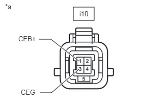
B517963C07
1.5,0.146 1.927,0.417 0.427,0.271 1.615,1.25 1.042,0.802 1.042,0.802 0.802,0.802 true 1.625,1.406 1.052,1.896 1.052,1.896 0.813,1.896 true 0.104,0.052 0.417,0.208 0.313,0.156 10 false *a 1.625,0.198 2.083,0.396 0.458,0.198 10 false i10 0.375,0.708 0.99,0.906 0.615,0.198 10 false CEB+ 0.427,1.802 0.906,1.99 0.479,0.188 10 false CEG
*a Front view of wire harness connector
(to Inner Mirror Camera Assembly)


Disconnect the inner mirror camera assembly connector.


b.

Measure the voltage according to the value(s) in the table below.

Standard Voltage:
Tester Connection Switch Condition Specified Condition
i10-1 (CEB+) - i10-3 (CEG) Ignition switch ON 5.5 V or higher


Result:
Proceed to
OK
NG


OK

3.CHECK INNER MIRROR CAMERA ASSEMBLY

NG

REPLACE INNER REAR VIEW MIRROR ASSEMBLY

3.CHECK INNER MIRROR CAMERA ASSEMBLY
a.

Temporarily replace the inner mirror camera assembly with a new or normally functioning one.

Click hereVehicle Interior>MIRROR (INT)>INNER MIRROR MONITOR CAMERA>REMOVAL


b.

Check that the digital rear-view mirror system is operating normally.

OK:

The digital rear-view mirror system is operating normally.


Result:
Proceed to
OK
NG


OK

END (INNER MIRROR CAMERA ASSEMBLY IS DEFECTIVE)

NG

REPLACE INNER REAR VIEW MIRROR ASSEMBLY

4.CHECK HARNESS AND CONNECTOR (INNER REAR VIEW MIRROR ASSEMBLY - MIRROR CAMERA WIRE)
a.
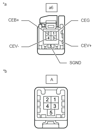
E418856C01
1.552,0.115 1.927,0.396 0.375,0.281 1.552,2.51 1.927,2.792 0.375,0.281 1.865,1.104 2.406,0.688 2.406,0.688 2.635,0.688 true 1.854,1.271 2.406,1.542 2.406,1.542 2.635,1.542 true 1.604,1.125 0.969,0.688 0.969,0.688 0.719,0.688 true 1.583,1.292 0.969,1.563 0.969,1.563 0.719,1.563 true 1.708,1.552 2.021,2.104 2.021,2.104 2.25,2.104 true 1.646,0.167 1.958,0.365 0.313,0.198 10 false a6 1.698,2.573 1.854,2.771 0.156,0.198 10 false A 2.729,0.594 3.188,0.792 0.458,0.198 10 false CEG 2.729,1.438 3.188,1.635 0.458,0.198 10 false CEV+ 0.281,0.583 0.74,0.781 0.458,0.198 10 false CEB+ 2.344,2.01 2.802,2.208 0.458,0.198 10 false SGND 0.313,1.458 0.771,1.656 0.458,0.198 10 false CEV- 0.094,0.052 0.406,0.208 0.313,0.156 10 false *a 0.104,2.292 0.563,2.49 0.458,0.198 10 false *b
*a Front view of wire harness connector
(to Inner Rear View Mirror Assembly)
*b Front view of wire harness connector
(to Mirror Camera Wire)


for Stadardard Roof:

i.

Disconnect the a6 inner rear view mirror assembly connector.


ii.

Disconnect the A mirror camera wire connector.


iii.

Measure the resistance according to the value(s) in the table below.

Tester Connection Condition Specified Condition
a6-1 (CEG) - A-1 Always Below 1 Ω
a6-2 (CEB+) - A-2 Always Below 1 Ω
a6-3 (CEV+) - A-3 Always Below 1 Ω
a6-4 (CEV-) - A-4 Always Below 1 Ω
a6-5 (SGND) - A-5 Always Below 1 Ω
a6-1 (CEG) or A-1 - Body ground Always 10 kΩ or higher
a6-2 (CEB+) or A-2 - Body ground Always 10 kΩ or higher
a6-3 (CEV+) or A-3 - Body ground Always 10 kΩ or higher
a6-4 (CEV-) or A-4 - Body ground Always 10 kΩ or higher
a6-5 (SGND) or A-5 - Body ground Always 10 kΩ or higher


b.
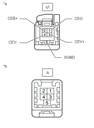
E418856C02
1.552,0.115 1.927,0.396 0.375,0.281 1.552,2.51 1.927,2.792 0.375,0.281 1.865,1.104 2.406,0.688 2.406,0.688 2.635,0.688 true 1.854,1.271 2.406,1.542 2.406,1.542 2.635,1.542 true 1.604,1.125 0.969,0.688 0.969,0.688 0.719,0.688 true 1.583,1.292 0.969,1.563 0.969,1.563 0.719,1.563 true 1.708,1.552 2.021,2.104 2.021,2.104 2.25,2.104 true 1.667,0.167 1.979,0.365 0.313,0.198 10 false q1 1.698,2.573 1.854,2.771 0.156,0.198 10 false A 2.729,0.594 3.188,0.792 0.458,0.198 10 false CEG 2.729,1.438 3.188,1.635 0.458,0.198 10 false CEV+ 0.281,0.583 0.74,0.781 0.458,0.198 10 false CEB+ 2.344,2.01 2.802,2.208 0.458,0.198 10 false SGND 0.313,1.458 0.771,1.656 0.458,0.198 10 false CEV- 0.125,0.052 0.438,0.208 0.313,0.156 10 false *a 0.125,2.333 0.438,2.49 0.313,0.156 10 false *b
*a Front view of wire harness connector
(to Inner Rear View Mirror Assembly)
*b Front view of wire harness connector
(to Mirror Camera Wire)


for High Roof:

i.

Disconnect the q1 inner rear view mirror assembly connector.


ii.

Disconnect the A mirror camera wire connector.


iii.

Measure the resistance according to the value(s) in the table below.

Tester Connection Condition Specified Condition
q1-1 (CEG) - A-1 Always Below 1 Ω
q1-2 (CEB+) - A-2 Always Below 1 Ω
q1-3 (CEV+) - A-3 Always Below 1 Ω
q1-4 (CEV-) - A-4 Always Below 1 Ω
q1-5 (SGND) - A-5 Always Below 1 Ω
q1-1 (CEG) or A-1 - Body ground Always 10 kΩ or higher
q1-2 (CEB+) or A-2 - Body ground Always 10 kΩ or higher
q1-3 (CEV+) or A-3 - Body ground Always 10 kΩ or higher
q1-4 (CEV-) or A-4 - Body ground Always 10 kΩ or higher
q1-5 (SGND) or A-5 - Body ground Always 10 kΩ or higher


Result:
Proceed to
OK
NG


OK

NG

REPAIR OR REPLACE HARNESS OR CONNECTOR