RM35X0E
_59
Vehicle Exterior
_079320
WIPER / WASHER
_0385301
WIPER AND WASHER SYSTEM
U
WIPER / WASHER WIPER AND WASHER SYSTEM TERMINALS OF ECU
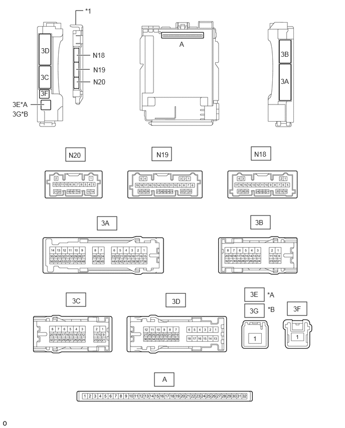
CHECK INSTRUMENT PANEL JUNCTION BLOCK ASSEMBLY AND MAIN BODY ECU (MULTIPLEX NETWORK BODY ECU)
3.208,7.729 3.615,8.01
0.406,0.281
5.969,6.26 6.375,6.542
0.406,0.281
2.021,4.49 2.427,4.771
0.406,0.281
5.208,4.469 5.615,4.75
0.406,0.281
1.375,6.073 1.781,6.354
0.406,0.281
3.448,6.083 3.854,6.365
0.406,0.281
5.083,5.969 5.49,6.25
0.406,0.281
5.083,6.302 5.49,6.583
0.406,0.281
3.156,3.052 3.563,3.333
0.406,0.281
5.219,3.042 5.625,3.323
0.406,0.281
1.365,3.063 1.771,3.344
0.406,0.281
0.635,2.167 0.917,2.167
true
1.583,1.438 1.865,1.438
true
1.594,1.698 1.875,1.698
true
1.594,1.146 1.875,1.146
true
1.573,0.51 1.573,0.219
1.573,0.219 1.729,0.219
false
0.854,0.969 1.167,1.167
0.313,0.198
10
false
3D
0.844,1.521 1.156,1.719
0.313,0.198
10
false
3C
0.844,1.854 1.156,2.052
0.313,0.198
10
false
3F
5.833,1.042 6.146,1.24
0.313,0.198
10
false
3B
5.833,1.604 6.146,1.802
0.313,0.198
10
false
3A
0.26,2.083 0.875,2.281
0.615,0.198
10
false
3E*A
0.26,2.281 0.875,2.479
0.615,0.198
10
false
3G*B
3.729,0.833 3.885,1.031
0.156,0.198
10
false
A
3.375,7.781 3.531,7.979
0.156,0.198
10
false
A
6.094,6.323 6.406,6.521
0.313,0.198
10
false
3F
2.104,4.542 2.417,4.74
0.313,0.198
10
false
3A
5.302,4.531 5.615,4.729
0.313,0.198
10
false
3B
1.5,6.156 1.813,6.354
0.313,0.198
10
false
3C
3.573,6.167 3.885,6.365
0.313,0.198
10
false
3D
5.198,6.021 5.51,6.219
0.313,0.198
10
false
3E
5.188,6.365 5.5,6.563
0.313,0.198
10
false
3G
5.552,6.031 5.865,6.229
0.313,0.198
10
false
*A
5.563,6.333 5.875,6.531
0.313,0.198
10
false
*B
3.25,3.125 3.708,3.323
0.458,0.198
10
false
N19
5.281,3.115 5.74,3.313
0.458,0.198
10
false
N18
1.427,3.135 1.885,3.333
0.458,0.198
10
false
N20
1.938,1.365 2.396,1.563
0.458,0.198
10
false
N19
1.938,1.615 2.396,1.813
0.458,0.198
10
false
N20
1.927,1.063 2.385,1.26
0.458,0.198
10
false
N18
1.771,0.146 2.083,0.344
0.313,0.198
10
false
*1
| *A | for LHD | *B | for RHD |
| *1 | Main Body ECU (Multiplex Network Body ECU) | - | - |
a.
Measure the voltage and check for pulses according to the value(s) in the table below.
| Terminal No. (Symbol) | Wiring Color | Terminal Description | Condition | Specified Condition |
|---|---|---|---|---|
|
*: w/ Rear Wiper |
||||
| N20-5 (CXP1) - Body ground | Y - Body ground | CXPI communication line | Ignition switch ON | Pulse generation |
| N19-21 (WPS) - Body ground | P - Body ground | Windshield wiper relay (WIPER) operation signal | Ignition switch ON | 11 to 14 V |
| Less than approximately 60 seconds after ignition switch off | ||||
| Approximately 60 seconds or more after ignition switch off | Below 1 V | |||
| N18-1 (RMRY) - Body ground* | BE - Body ground | Rear wiper motor assembly operation signal | Rear wiper motor assembly stopped | 11 to 14 V |
| Rear wiper motor assembly operating | Below 1 V | |||
CHECK WINDSHIELD WIPER RELAY ASSEMBLY

2.719,0.125 3.125,0.333
0.406,0.208
3.844,0.125 4.25,0.333
0.406,0.208
2.802,0.146 3.26,0.344
0.458,0.198
10
false
N68
3.927,0.146 4.385,0.344
0.458,0.198
10
false
N67
a.
Disconnect the N67 and N68 windshield wiper relay assembly connectors.
b.
Measure the voltage and resistance according to the value(s) in the table below.
| Terminal No. (Symbol) | Wiring Color | Terminal Description | Condition | Specified Condition |
|---|---|---|---|---|
| N67-3 (E) - Body ground | W-B - Body ground | Ground | Always | Below 1 Ω |
| N67-5 (EWS) - Body ground | BR - Body ground | Ground | Always | Below 1 Ω |
| N67-6 (IGWS) - Body ground | BE - Body ground | Washer circuit IG power source | Ignition switch off | Below 1 V |
| Ignition switch ON | 11 to 14 V | |||
| N67-8 (+B) - Body ground | B - Body ground | Ignition switch signal (Power source circuit) | Ignition switch ON | 11 to 14 V |
| Less than approximately 60 seconds after ignition switch off | ||||
| Approximately 60 seconds or more after ignition switch off | Below 1 V | |||
| N68-5 (ES) - Body ground | W-B - Body ground | Ground | Always | Below 1 Ω |
c.
Connect the N67 and N68 windshield wiper relay assembly connectors.
d.
Measure the voltage and check for pulses according to the value(s) in the table below.
| Terminal No. (Symbol) | Wiring Color | Terminal Description | Condition | Specified Condition |
|---|---|---|---|---|
|
*: w/ Rear Wiper |
||||
| N67-1 (+WR) - Body ground | V - Body ground | Front washer operation signal | Ignition switch ON, front washer operating | 11 to 14 V |
| N67-2 (+1) - Body ground | L - Body ground | LO operation signal to windshield wiper motor assembly | Ignition switch ON, windshield wiper motor assembly operating in LO | 11 to 14 V |
| N67-4 (+2) - Body ground | R - Body ground | HI operation signal to windshield wiper motor assembly | Ignition switch ON, windshield wiper motor assembly operating in HI | 11 to 14 V |
| N67-7 (-WR) - Body ground* | P - Body ground | Rear washer operation signal | Ignition switch ON, rear washer operating | 11 to 14 V |
| N68-3 (2S) - Body ground | B - Body ground | Windshield wiper motor assembly HI operation signal | Approximately 60 seconds or more after ignition switch off | 4.5 to 5.5 V |
| Windshield wiper motor assembly operating in LO | 9 to 14 V | |||
| Windshield wiper motor assembly operating in HI | Below 1 V | |||
| N68-4 (MPX1) - Body ground | Y - Body ground | CXPI communication line | Ignition switch ON | Pulse generation |
| N68-6 (+SM) - Body ground | G - Body ground | Windshield wiper motor assembly position detection signal | Windshield wiper motor assembly in LO or HI operation | Below 1 V ←→ 10 to 14 V |
| Windshield wiper motor assembly stopped | Below 1 V | |||