RM35X0E
_52
Drivetrain
_078740
RC60J MANUAL TRANSMISSION / TRANSAXLE
_0383350
MANUAL TRANSMISSION SYSTEM(for 1GD-FTV)
U
RC60J MANUAL TRANSMISSION / TRANSAXLE MANUAL TRANSMISSION SYSTEM(for 1GD-FTV) TERMINALS OF ECM
ECM
0.635,0.656 0.969,0.844
0.333,0.188
1.771,0.646 2.135,0.833
0.365,0.188
2.99,0.646 3.354,0.833
0.365,0.188
3.99,0.646 4.354,0.833
0.365,0.188
5.052,0.646 5.417,0.833
0.365,0.188
6.188,0.646 6.552,0.833
0.365,0.188
0.729,0.667 1.042,0.865
0.313,0.198
10
false
E5
1.875,0.656 2.188,0.854
0.313,0.198
10
false
E6
3.104,0.656 3.417,0.854
0.313,0.198
10
false
E7
4.094,0.656 4.406,0.854
0.313,0.198
10
false
E8
5.167,0.656 5.479,0.854
0.313,0.198
10
false
N2
6.292,0.656 6.604,0.854
0.313,0.198
10
false
A2
- HINT:
-
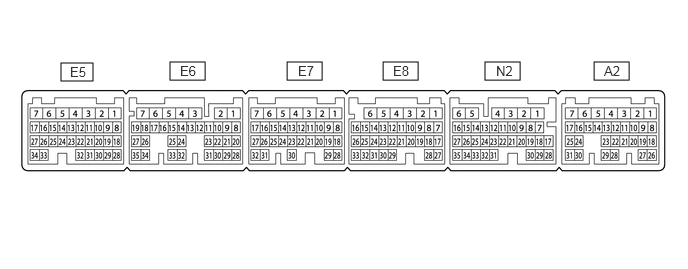
The standard voltage and resistance of each ECM terminal is shown in the table below.
-
In the table, first follow the information under "Condition". Look under "Terminal No. (Symbol)" for the terminals to be inspected. The standard voltage or resistance between the terminals is shown under "Specified Condition".
-
Use the illustration above as a reference for the ECM terminals.
| Terminal No. (Symbol) | Wiring Color | Terminal Description | Condition | Specified Condition |
|---|---|---|---|---|
| A2-20 (CLS) - A2-21 (E2CL) | G - BR | Clutch pedal stroke sensor assembly signal | Ignition switch ON and clutch pedal fully released | 0.96 to 1.04 V |
·
Ignition switch ON ·
Not depressed → Fully depressed (Clutch pedal should be operated slowly) |
Value changes progressively (Only increase) | |||
| A2-23 (VCCL) - A2-5 (E1) | W - W-B | Power supply for clutch pedal stroke sensor assembly | Ignition switch ON | 4.5 to 5.5 V |
| E7-12 (NIMB) - A2-5 (E1) | B - W-B | Power supply for transmission revolution sensor | Ignition switch ON | 11 to 14 V |
| E7-13 (NIMO) - A2-5 (E1) | W - W-B | Transmission revolution sensor signal | Engine idling and clutch pedal fully released | Pulse generation |
| N2-8 (MTMS) - A2-5 (E1) | B - W-B | iMT switch signal | Ignition switch ON and iMT switch pushed | Below 1.5 V |
| Ignition switch ON and iMT switch not pushed | 11 to 14 V | |||
| N2-17 (CANH) - A2-5 (E1) | G - W-B | CAN communication line | Ignition switch ON | Pulse generation |
| N2-28 (CANL) - A2-5 (E1) | W - W-B | CAN communication line | Ignition switch ON | Pulse generation |