POWER ASSIST SYSTEMS VANE PUMP(for 7GR-FKS(w/ Variable Flow Control Solenoid Valve)) INSPECTION
PROCEDURE

 1.INSPECT CLEARANCE BETWEEN VANE PUMP SHAFT AND BUSHING IN FRONT HOUSING
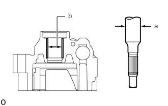
Using a micrometer, measure the diameter (a) of the shaft with pulley.
Using a caliper gauge, measure the inside diameter (b) of the front housing.
- NOTICE:
-
Do not damage the bushing in the front housing.
Subtract (a) from (b) to calculate the oil clearance.
- Maximum clearance:
0.07 mm (0.00276 in.)
If the clearance is more it is more than the maximum, replace the shaft with pulley.
2.INSPECT VANE PUMP ROTOR AND VANE PUMP PLATES CLEARANCE
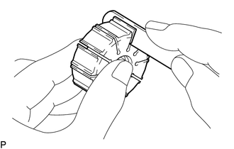
Using a feeler gauge, measure the clearance between the side face of the vane pump rotor groove and the vane pump plates.
- Maximum clearance:
0.025 mm (0.000984 in.)
If the clearance is more than the maximum, replace the vane pump plates, vane pump rotor and vane pump cam ring.
- HINT:
-
Refer to the following table to select an appropriate combination of vane pump rotor, vane pump cam ring and vane pump plates.
- Combination of Vane Pump Rotor, Vane Pump Cam Ring and Vane Pump Plates:
Vane Pump Cam Ring Part No. Vane Pump Rotor Part No. Vane Plate Part No. 44325-60080 44313-60010 44345-60060 44325-60090 44313-60020 44345-60070 44325-60100 44313-60030 44345-60080 44325-60110 44313-60040 44345-60090
3.INSPECT PRESSURE PORT UNION
If the union seat in the pressure port union sub-assembly is severely damaged, replace the pressure port union sub-assembly.