1GD-FTV ENGINE CONTROL ECD SYSTEM(w/ Exhaust Gas Temperature Sensor for EGR) DIAGNOSIS SYSTEM
EURO-OBD

When troubleshooting Europe On-Board Diagnostic (Euro-OBD) vehicles, the vehicle must be connected to the GTS. Various data output from the vehicle Engine Control Module (ECM) can then be read.
The Malfunction Indicator Lamp (MIL) is illuminated when the vehicle on-board computer detects a malfunction in the computer itself or in drive system components. In addition, the applicable Diagnostic Trouble Codes (DTCs) are stored in the ECM memory (Click here Engine / Hybrid System>1GD-FTV (ENGINE CONTROL)>ECD SYSTEM (w/ Exhaust Gas Temperature Sensor for EGR)>DIAGNOSTIC TROUBLE CODE CHART).
When the malfunction does not reoccur, the MIL stays illuminated until the engine switch is turned off, and the MIL turns off when the engine is started. Be aware that the DTCs remain stored in the ECM memory.
To check DTCs, connect the GTS to the DLC3 on the vehicle.
NORMAL MODE AND CHECK MODE
The diagnosis system operates in "normal mode" during normal vehicle use. In normal mode, "2 trip detection logic" is used to ensure accurate detection of malfunctions. "Check mode" is also available to technicians as an option. In check mode, "1 trip detection logic" is used when simulating malfunction symptoms to increase the ability of the system to detect malfunctions, including intermittent malfunctions (Click here Engine / Hybrid System>1GD-FTV (ENGINE CONTROL)>ECD SYSTEM (w/ Exhaust Gas Temperature Sensor for EGR)>CHECK MODE PROCEDURE).
2 TRIP DETECTION LOGIC
When a malfunction is first detected, the malfunction is temporarily stored in the ECM memory (1st trip). If the same malfunction is detected during the next subsequent drive cycle, the MIL is illuminated (2nd trip).
FREEZE FRAME DATA
The ECM records vehicle and driving condition information as freeze frame data the moment a DTC is stored. When troubleshooting, freeze frame data can be helpful in determining whether the vehicle was moving or stationary, whether the engine was warmed up or not, as well as other data recorded at the time of a malfunction.
BATTERY VOLTAGE
- Standard voltage:
11 to 14 V
If the voltage is below 11 V, recharge or replace the battery before proceeding.
MIL ILLUMINATION PATTERN
MIL (Malfunction Indicator Lamp) displays according to the vehicle condition.
- HINT:
-
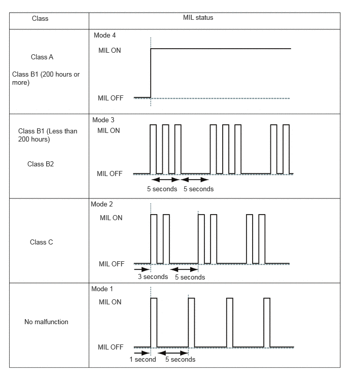
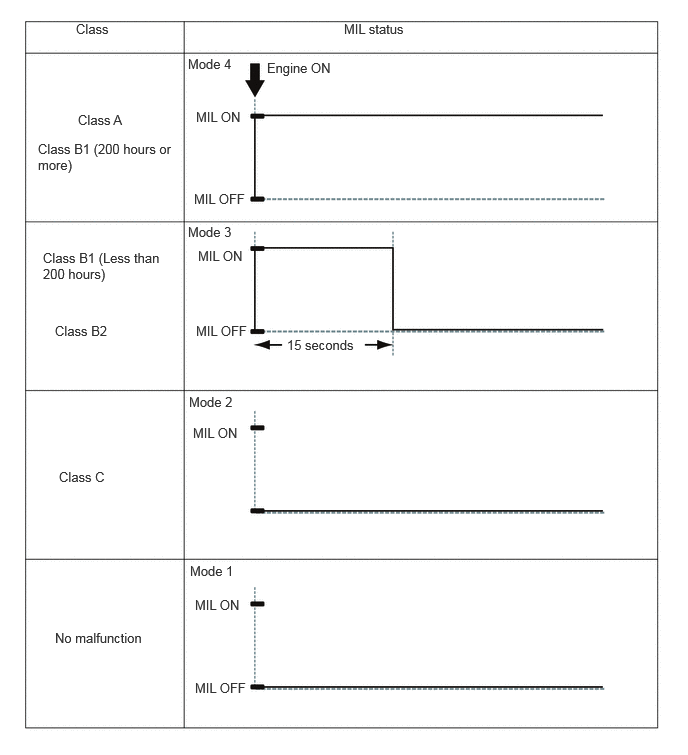
MIL display depends on malfunction class of each DTC.
Malfunction Class Requirement Class A Malfunction where exhaust gas components exceed the OBD threshold Class B1 Malfunction where exhaust gas components may exceed the OBD threshold Class B2 Malfunction where it is predicted that exhaust gas components will not reach a level that exceeds the OBD threshold Class C Malfunction where it is predicted that exhaust gas components will not reach a level that exceeds the regulation value
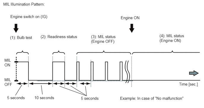
Refer to below for the relation between MIL display of (1) to (4) and its description.
(1): Bulb test
Bulb operational: MIL ON
Bulb non operational: MIL OFF
- HINT:
-
If the MIL is not illuminated, check the MIL circuit.
(2): Readiness status
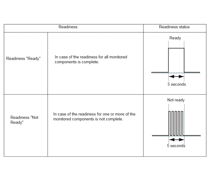
- HINT:
-
There are some items that cannot be determined if the engine is not running during troubleshooting. Therefore, when the engine switch is normally turned on (IG), the MIL blinks 5 times to indicate "Not ready".
-
(Even though it indicates "Not ready", this is not a malfunction.)
(3): MIL status (Engine OFF)
- HINT:
- ·
This sequence is repeated until the engine starts or the engine switch is turned off.
·For "Class B1", the MIL status changes from Mode 3 to Mode 4 (continuous illumination) if the cumulative elapsed time exceeds 200 hours after it is detected.
(4): MIL status (Engine ON)
- HINT:
-
For "Class B1", the MIL status changes from Mode 3 to Mode 4 (continuous illumination) if the cumulative elapsed time exceeds 200 hours after it is detected.
ALL READINESS
- HINT:
- ·
With "All Readiness", you can use the GTS to check whether or not the DTC judgment has been completed.
·You should check "All Readiness" after simulating malfunction symptoms or for validation after finishing repairs.
Connect the GTS to the DLC3.
Turn the engine switch on (IG).
Turn the GTS on.
Clear the DTCs.
- Powertrain > Engine and Transmission > Clear DTCs
- 50002 456
Turn the engine switch off and wait for at least 30 seconds.
Turn the engine switch on (IG).
Turn the GTS on.
Perform the DTC judgment driving pattern to run the DTC judgment.
Enter the following menus: Powertrain / Engine and Transmission / Utility / All Readiness.
- Powertrain > Engine and Transmission > Utility
-
Tester Display All Readiness - 50005 456 20
Input the DTCs to be confirmed.
Check the DTC judgment result.
| GTS Display | Description |
|---|---|
| NORMAL | ·
DTC judgment completed ·
System normal |
| ABNORMAL | ·
DTC judgment completed ·
System abnormal |
| INCOMPLETE | ·
DTC judgment not completed ·
Perform driving after confirming DTC enabling conditions |
DIAGNOSIS RELATED INFORMATION
- HINT:
- ·
If the detection conditions of certain DTCs are met before a malfunction can be confirmed, the ECM will store Diagnosis Related Information. Vehicle condition information from when the detection conditions were met can be checked using the Diagnosis Related Information. Diagnosis Related Information should be used as a reference only, and should not be relied upon solely when determining whether a part is faulty or not.
·Clearing DTCs will also clear Diagnosis Related Information.
·DTCs and Diagnosis Related Information are saved in the GTS at the same time.
Connect the GTS to the DLC3.
Turn the engine switch on (IG).
Turn the GTS on.
Enter the following menus: Powertrain / Engine and Transmission / Utility / Diagnosis Related Information.
- Powertrain > Engine and Transmission > Utility
-
Tester Display Diagnosis Related Information - 50005 456 56
Select a Diagnosis Related Information item to display its details.