INSTALLATION
Removal / installation · Vehicles built from Jul 2010
Versions by build date: May 2007 – Jul 2008 Aug 2008 – Jun 2010 from Jul 2010
| 1. INSTALL FRONT AIRBAG SENSOR |

Check that the ignition switch is off.
Check that the battery negative (-) cable is disconnected.
- CAUTION:
- Wait for at least 90 seconds after disconnecting the cable to prevent airbag deployment.
Temporarily install the front airbag sensor with the 2 claws and pin.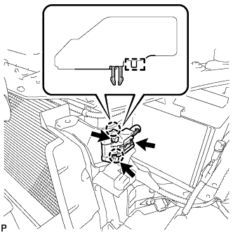

Install the front airbag sensor with the 2 bolts.
- Torque:
- 9.0 N*m{ 92 kgf*cm , 80 in.*lbf }
- NOTICE:
- If the front airbag sensor has been dropped, or there are any cracks, dents or other defects in the case, bracket or connector, replace it with a new one.
- When installing the front airbag sensor, be careful that the SRS wiring does not interfere with other parts and that it is not pinched between other parts.
- Make sure that the pin is securely inserted into the body hole.
- Tighten the bolt while holding the front airbag sensor because the front airbag sensor claws and pin (stopper) are easily damaged.
- If the front airbag sensor has been dropped, or there are any cracks, dents or other defects in the case, bracket or connector, replace it with a new one.
Check that there are no loose parts after installing the front airbag sensor.
Connect the connector to the front airbag sensor.
- NOTICE:
- When handling the airbag connector, take care not to damage the airbag wire harness.
| 2. INSTALL HEADLIGHT ASSEMBLY |
Connect the connectors and engage the clamp.
Engage the claw and install the headlight assembly with the bolt and 2 screws.
- Torque:
- 3.6 N*m{ 37 kgf*cm , 32 in.*lbf }
Engage the guide as shown in the illustration.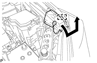
| 3. INSTALL FRONT BUMPER ASSEMBLY |
Connect each fog light connector, and then install the front bumper assembly.
Engage the 5 claws.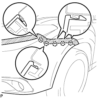
- HINT:
- Use the same procedure for the RH side and LH side.
Install the 3 clips and 8 screws.
Install the screw and 2 pin hold clips.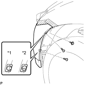
Text in Illustration *1
Correct
*2
Incorrect
- NOTICE:
- Insert the pin hold clip with the slot aligned vertically. Do not rotate the clip after inserting it. After installation, confirm that the slot is aligned vertically.
- HINT:
- Use the same procedure for the RH side and LH side.
| 4. INSTALL RADIATOR GRILLE SUB-ASSEMBLY |
Engage the 2 guides and 8 claws, and install the radiator grille sub-assembly.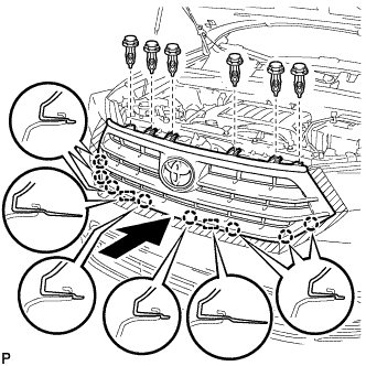
Install the 6 clips.
| 5. INSTALL COOL AIR INTAKE DUCT SEAL |
Install the cool air intake duct seal with the 11 clips.
| 6. CONNECT CABLE TO NEGATIVE BATTERY TERMINAL |
- NOTICE:
- When disconnecting the cable, some systems need to be initialized after the cable is reconnected (Click here).
| 7. INSPECT AND ADJUST HEADLIGHT AIMING |
| 8. INSPECT AND ADJUST FOG LIGHT AIMING |
| 9. INSPECT SRS WARNING LIGHT |
Inspect the SRS warning light (Click here).