REASSEMBLY
Removal / installation · Vehicles built from Jul 2010
Versions by build date: May 2007 – Jun 2010 from Jul 2010
| 1.
INSTALL STEERING LOCK ACTUATOR ASSEMBLY (w/ Smart Entry and Start System) |
 |
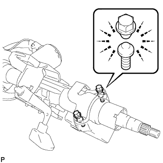
Temporarily install the steering lock actuator assembly and the steering lock bracket with 2 new tapered-head bolts.
- Tighten the 2 tapered-head bolts until the bolt heads break off.
| 2.
INSTALL IGNITION OR STARTER SWITCH ASSEMBLY (w/o Smart Entry and Start System) |
|
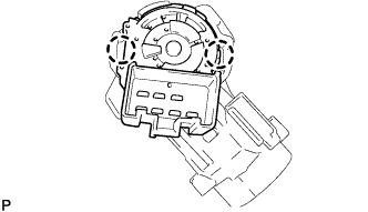
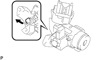
- Engage the 2 claws to install the ignition or starter switch assembly to the steering lock sub-assembly.
| 3.
INSTALL KEY INTERLOCK SOLENOID (w/o Smart Entry and Start System) |
|
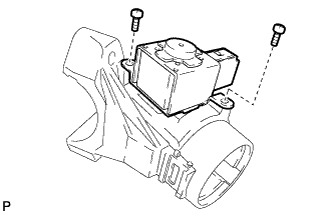
- Install the key interlock solenoid to the steering lock sub-assembly with the 2 screws.
| 4.
INSTALL UN-LOCK WARNING SWITCH ASSEMBLY (w/o Smart Entry and Start System) |
|
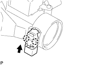
- Engage the 2 claws to install the un-lock warning switch assembly to the steering lock sub-assembly.
| 5.
INSTALL IGNITION SWITCH LOCK CYLINDER ASSEMBLY (w/o Smart Entry and Start System) |
|
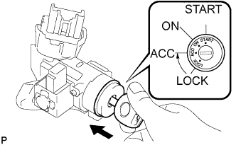
Make sure that the ignition switch lock cylinder assembly is in the ACC position.
- Install the ignition switch lock cylinder assembly to the steering lock sub-assembly.
Make sure that the ignition switch lock cylinder assembly is securely installed.
| 6.
INSPECT STEERING LOCK OPERATION (w/o Smart Entry and Start System)
|
|
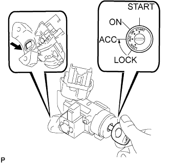
- Check that the steering lock mechanism is activated when the key is removed.
- Check that the steering lock mechanism is deactivated when the key is inserted and turned to the ACC position.
- HINT:
- If there is any abnormality, replace the ignition switch lock cylinder assembly.
| 7.
INSTALL STEERING COLUMN UPPER WITH SWITCH BRACKET ASSEMBLY (w/o Smart Entry and Start System) |
|
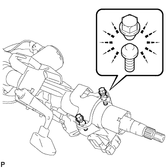
Temporarily install the assembled steering lock and its bracket to the steering column assembly with 2 new tapered-head bolts.
- Tighten the 2 tapered-head bolts until the bolt heads break off.
| 8.
INSTALL TRANSPONDER KEY AMPLIFIER (w/o Smart Entry and Start System) |
|
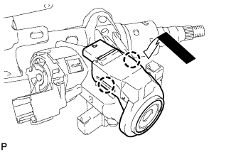
- Align the transponder key amplifier with the upper bracket. Tilt the amplifier slightly and slide it into the position as shown in the illustration.
Push the transponder key amplifier to install it to the upper bracket with the 2 claws.
- NOTICE:
- Do not push the amplifier with excessive force.