TERMINALS OF ECU
System information · Vehicles built from May 2007
| CHECK CERTIFICATION ECU (SMART KEY ECU ASSEMBLY) |
Disconnect the D36 certification ECU (smart key ECU assembly) connector.
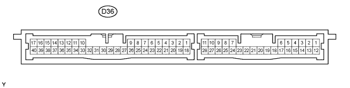

Measure the voltage and resistance according to the value(s) in the table below.
If the result is not as specified, the wire harness may have a malfunction.Tester Connection
Wiring Color
Terminal Description
Condition
Specified Condition
D36-1 (+B) - Body ground
B - Body ground
+B power supply
Always
11 to 14 V
D36-3 (TSW1) - Body ground
LG - Body ground
Entry lock switch (driver side) signal
Front lock switch not pushed
10 kΩ or higher
D36-3 (TSW1) - Body ground
LG - Body ground
Entry lock switch (driver side) signal
Front lock switch pushed
Below 1 Ω
D36-4 (TSW2) - Body ground
GR - Body ground
Entry lock switch (front passenger side) signal
Front lock switch not pushed
10 kΩ or higher
D36-4 (TSW2) - Body ground
GR - Body ground
Entry lock switch (front passenger side) signal
Front lock switch pushed
Below 1 Ω
D36-7 (TSW5) - Body ground
BR - Body ground
Back door entry lock switch signal
Lock switch OFF
10 kΩ or higher
D36-7 (TSW5) - Body ground
BR - Body ground
Back door entry lock switch signal
Lock switch ON
Below 1 Ω
D36-10 (LIN) - Body ground
L - Body ground
LIN line
Always
10 kΩ or higher
D36-17 (E) - Body ground
B - Body ground
Ground
Always
Below 1 Ω
D36-18 (IG) - Body ground
G - Body ground
Ignition power supply
Engine switch off
Below 1 V
D36-18 (IG) - Body ground
G - Body ground
Ignition power supply
Engine switch on (IG)
11 to 14 V
D36-19 (ACC) - Body ground
SB - Body ground
ACC power supply
Engine switch off
Below 1 V
D36-19 (ACC) - Body ground
SB - Body ground
ACC power supply
Engine switch on (ACC)
11 to 14 V
D36-27 (CANH) - Body ground
GR - Body ground
CAN line
Always
10 kΩ or higher
D36-28 (CANL) - Body ground
W - Body ground
CAN line
Always
10 kΩ or higher
D36-40 (AGND) - Body ground
V - Body ground
Ground
Always
Below 1 Ω
Reconnect the D36 certification ECU (smart key ECU assembly) connector.
Measure the voltage and resistance according to the value(s) in the table below.
If the result is not as specified, the ECU may have a malfunction.Tester Connection
Wiring Color
Terminal Description
Condition
Specified Condition
D36-5 (SEL1) - D36-17 (E)
P - B
Touch sensor (driver side) activation control signal
The key is moved more than 5 m (16.4 ft.) away from the front door.
11 to 14 V
D36-5 (SEL1) - D36-17 (E)
P - B
Touch sensor (driver side) activation control signal
The key is moved to the door outside handle.
Below 1 V
D36-6 (SEL2) - D36-17 (E)
Y - B
Touch sensor (front passenger side) activation control signal
The key is moved more than 5 m (16.4 ft.) away from the front passenger door.
11 to 14 V
D36-6 (SEL2) - D36-17 (E)
Y - B
Touch sensor (front passenger side) activation control signal
The key is moved to the door outside handle.
Below 1 V
D36-8 (TXCT) - Body ground
O - Body ground
Transponder key amplifier output signal
Electrical key is not in the cabin.
Below 1 V
D36-8 (TXCT) - Body ground
O - Body ground
Transponder key amplifier output signal
Electrical key is outside the cabin and the driver's door is open.
Pulse generation (see waveform 1)
D36-9 (CODE) - Body ground
GR - Body ground
Transponder key amplifier communication signal
Electrical key is not in the cabin.
Below 1 V
D36-9 (CODE) - Body ground
GR - Body ground
Transponder key amplifier communication signal
Electrical key is outside the cabin and the driver's door is open. Electrical key is held close to the engine switch with the brake pedal depressed.
Pulse generation (see waveform 2)
D36-11 (CLG5) - D36-12 (CG5B)
R - W
Indoor electrical key oscillator (front) sensor signal
Within 30 seconds after driver side door opened and closed, engine switch off
Alternating between 5 V and below -5 V
D36-11 (CLG5) - D36-12 (CG5B)
R - W
Indoor electrical key oscillator (front) sensor signal
Engine switch on (IG)
Below 1 V
D36-13 (CLG6) - D36-14 (CG6B)
R - SB
Indoor electrical key oscillator (center) sensor signal
Within 30 seconds after driver side door opened and closed, engine switch off
Alternating between 5 V and below -5 V
D36-13 (CLG6) - D36-14 (CG6B)
R - SB
Indoor electrical key oscillator (center) sensor signal
Engine switch on (IG)
Below 1 V
D36-15 (CLG7) - D36-16 (CG7B)
G - O
Indoor electrical key oscillator (rear) sensor signal
Within 30 seconds after driver side door opened and closed, engine switch off
Alternating between 5 V and below -5 V
D36-15 (CLG7) - D36-16 (CG7B)
G - O
Indoor electrical key oscillator (rear) sensor signal
Engine switch on (IG)
Below 1 V
D36-21 (BZR) - Body ground
R - Body ground
Wireless door lock buzzer signal
Wireless door lock buzzer OFF
Below 1 V
D36-21 (BZR) - Body ground
R - Body ground
Wireless door lock buzzer signal
Wireless door lock buzzer ON
Pulse generation
D36-22 (SEN1) - D36-17 (E)
O - B
Touch sensor (driver side) detection signal
Door outside handle touched
Below 1 V
D36-22 (SEN1) - D36-17 (E)
O - B
Touch sensor (driver side) detection signal
Door outside handle not touched (the electrical key is outside the cabin)
11 to 14 V
D36-23 (SEN2) - D36-17 (E)
W - B
Touch sensor (front passenger side) detection signal
Door outside handle touched
Below 1 V
D36-23 (SEN2) - D36-17 (E)
W - B
Touch sensor (front passenger side) detection signal
Door outside handle not touched (the electrical key is outside the cabin)
11 to 14 V
D36-29 (RC0) - D36-17 (E)
V - B
Entry door control receiver power source
Engine switch off, all doors closed and electrical key switch on
4.5 to 5.5 V
D36-29 (RC0) - D36-17 (E)
V - B
Entry door control receiver power source
Engine switch off, all doors closed and electrical key switch off
Below 1 V
D36-30 (VC5) - Body ground
G - Body ground
Transponder key amplifier power supply
Electrical key is not in the cabin.
Below 1 V
D36-30 (VC5) - Body ground
G - Body ground
Transponder key amplifier power supply
Electrical key is outside the cabin and the driver's door is open.
4.5 to 5.5 V
D36-31 (CLG8) - D36-32 (CG8B)
LG - P
Outside electrical key oscillator (back door) sensor signal
Back door opener switch ON
Alternating between 5 V and below -5 V
D36-31 (CLG8) - D36-32 (CG8B)
LG - P
Outside electrical key oscillator (back door) sensor signal
Back door opener switch OFF
Below 1 V
D36-33 (CLG1) - D36-17 (E)
GR - B
Door electrical key oscillator (driver side) sensor signal
All doors closed and locked and engine switch off
Alternating between 5 V and below 1 V
D36-33 (CLG1) - D36-17 (E)
GR - B
Door electrical key oscillator (driver side) sensor signal
Door unlocked or open
Below 1 V
D36-35 (CLG2) - D36-17 (E)
LG - B
Door electrical key oscillator (front passenger side) sensor signal
All doors closed and locked and engine switch off
Alternating between 5 V and below 1 V
D36-35 (CLG2) - D36-17 (E)
LG - B
Door electrical key oscillator (front passenger side) sensor signal
Door unlocked or open
Below 1 V
D36-38 (RDA) - D36-17 (E)
Y - B
Entry door control receiver data input signal
Engine switch off, all doors closed and electrical key switch off
11 to 14 V
(Pulse generation)
D36-38 (RDA) - D36-17 (E)
Y - B
Entry door control receiver data input signal
Engine switch off, all doors closed and electrical key switch on
Pulse generation
D36-38 (RDA) - Body ground
Y - Body ground
Tuner input signal
Engine switch off, all doors closed, and the electrical key is not in the detection area.
11 to 14 V
(Pulse generation)
D36-38 (RDA) - Body ground
Y - Body ground
Tuner input signal
The electrical key is in the detection area.
Pulse generation
D36-39 (RSSI) - D36-17 (E)
B - B
Entry door control receiver electric wave existence signal
Engine switch off, all doors closed, and the electrical key is not in the detection area.
11 to 14 V
D36-39 (RSSI) - D36-17 (E)
B - B
Entry door control receiver electric wave existence signal
Engine switch off, all doors closed, and the electrical key is in the detection area.
Below 1 V
Inspect using an oscilloscope.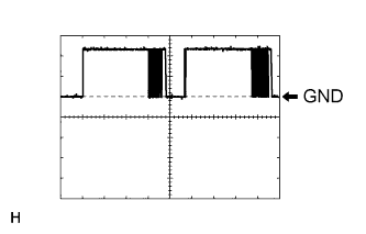
Waveform 1 (Reference): Tester Connection
D36-8 (TXCT) - Body ground
Tool Setting
2 V/DIV., 50 ms./DIV.
Condition
The electrical key is outside the cabin and the driver's door is open.
Inspect using an oscilloscope.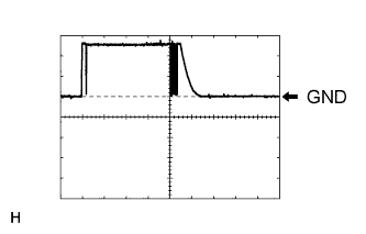
Waveform 2 (Reference): Tester Connection
D36-9 (CODE) - Body ground
Tool Setting
2 V/DIV., 50 ms./DIV.
Condition
The electrical key is outside the cabin and the driver's door is open. The electrical key is held close to the engine switch with the brake pedal depressed.
| MAIN BODY ECU (INSTRUMENT PANEL JUNCTION BLOCK) |
Disconnect the 1M and 1F junction block connectors.
Disconnect the D8 main body ECU (instrument panel junction block) connector.
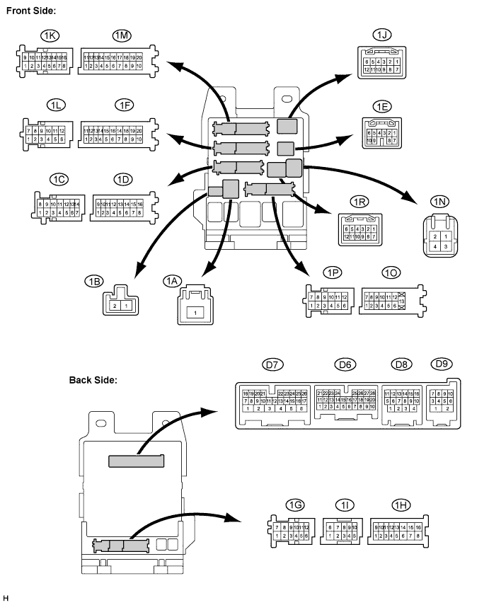
Measure the voltage and resistance according to the value(s) in the table below.
If the result is not as specified, the wire harness may have a malfunction.Tester Connection
Wiring Color
Terminal Description
Condition
Specified Condition
1M-9 (GND2) - Body ground
W-B - Body ground
Ground
Always
Below 1 Ω
1F-10 (GND1) - Body ground
W-B - Body ground
Ground
Always
Below 1 Ω
D8-15 (CANN) - Body ground
W - Body ground
CAN line
Always
10 kΩ or higher
D8-16 (CANP) - Body ground
Y - Body ground
CAN line
Always
10 kΩ or higher
Reconnect the 1M and 1F junction block connectors.
Reconnect the D8 main body ECU (instrument panel junction block ) connector.
Measure the voltage and resistance according to the value(s) in the table below.
If the result is not as specified, the ECU may have a malfunction.Tester Connection
Wiring Color
Terminal Description
Condition
Specified Condition
1M-7 (STP) - Body ground
GR - Body ground
Stop light switch signal
Brake pedal depressed
11 to 14 V
1M-7 (STP) - Body ground
GR - Body ground
Stop light switch signal
Brake pedal released
Below 1 V