2007-2013 Highlander Kluger · Service Manual ENGINE

REMOVAL

Removal / installation · Vehicles built May 2007 – Jul 2008

Versions by build date: May 2007 – Jul 2008 Aug 2008 – Jun 2010 from Jul 2010


1. DISCONNECT CABLE FROM NEGATIVE BATTERY TERMINAL

CAUTION:
Wait at least 90 seconds after disconnecting the cable from the negative (-) battery terminal to prevent airbag deployment and seat belt pretensioner activation.

NOTICE:
When disconnecting the cable, some systems need to be initialized after the cable is reconnected (Click here).


2. REMOVE STEERING COLUMN COVER LOWER

  1. A170650
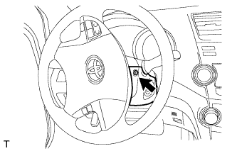
    Insert the key into the ignition key cylinder and release the steering lock.

  1. Turn the steering wheel clockwise to gain access to the screw and remove the screw.

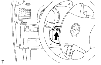
  1. A170651
    Turn the steering wheel counterclockwise to gain access to the screw and remove the screw.

  1. Release the tilt lever.

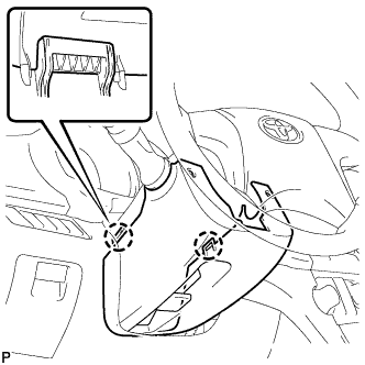
  1. A170657
    Disengage the 2 claws and remove the steering column cover lower.


3. REMOVE FRONT DOOR SCUFF PLATE LH

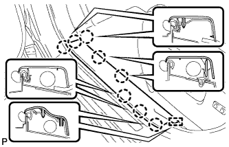
  1. B173224
    Disengage the 8 claws and guide, and remove the front door scuff plate LH.


4. REMOVE COWL SIDE TRIM SUB-ASSEMBLY LH

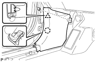
  1. B173227
    Remove the clip.

  1. Disengage the clip and claw, and remove the cowl side trim sub-assembly LH.


5. REMOVE LOWER INSTRUMENT PANEL FINISH PANEL SUB-ASSEMBLY (for Manual Air Conditioning System)

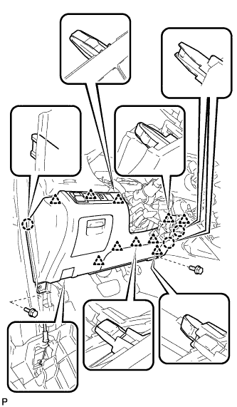
  1. B168371
    Remove the 2 bolts <B>.

  1. Disengage the 3 claws and 10 clips.

  1. Disconnect each connector.

  1. Disconnect the hood lock control cable assembly and remove the lower instrument panel finish panel sub-assembly.


6. REMOVE LOWER INSTRUMENT PANEL FINISH PANEL SUB-ASSEMBLY (for Automatic Air Conditioning System)

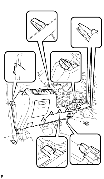
  1. B173021
    Remove the 2 bolts <B>.

  1. Disengage the 3 claws and 10 clips.

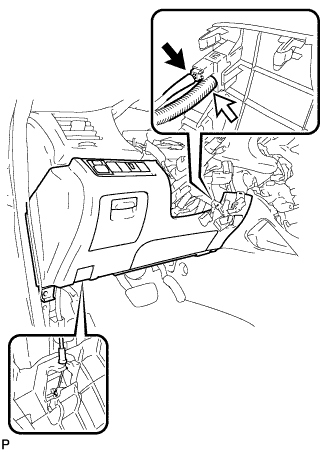
  1. B173009
    Disconnect each connector and the aspirator duct.

  1. Disconnect the hood lock control cable assembly and remove the lower instrument panel finish panel sub-assembly.


7. REMOVE IGNITION SWITCH ASSEMBLY

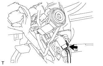
  1. A170652
    Disconnect the ignition switch connector.

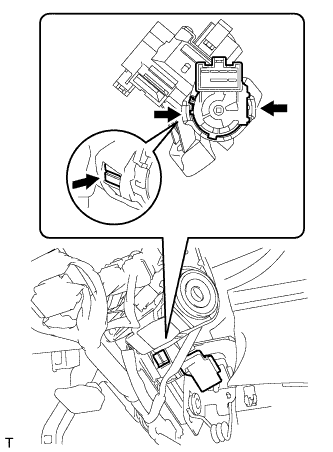
  1. A170653
    Disengage the 2 claws and remove the ignition switch.

← COMPONENTS (from May 2007)REMOVAL (Aug 2008 – Jun 2010) →