REMOVAL
Removal / installation · Vehicles built May 2007 – Jul 2008
Versions by build date: May 2007 – Jul 2008 Aug 2008 – Jun 2010 from Jul 2010
- HINT:
- Use the same procedures for the RH side and LH side.
- The procedures listed below are for the LH side.
| 2.
REMOVE DECK SIDE TRIM COVER
|
 |
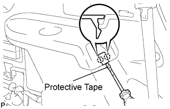
- Using a screwdriver, disengage the 2 claws and remove the deck side trim cover LH.
- HINT:
- Tape the screwdriver tip before use.
| 3.
REMOVE DECK SIDE TRIM
|
|
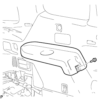
- Remove the bolt.
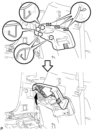
- Disengage the 4 claws and the 3 guides, and remove the deck side trim LH as shown in the illustration.
| 4.
SEPARATE REAR FLEXIBLE HOSE (for 2WD) |
|
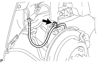
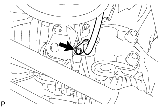
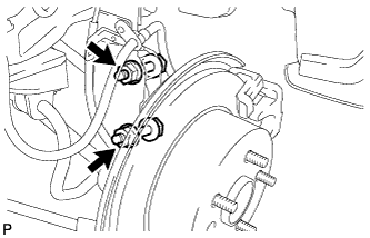
- Remove the bolt and separate the rear flexible hose from the rear shock absorber with coil spring.
| 5.
SEPARATE REAR FLEXIBLE HOSE (for 4WD) |
|
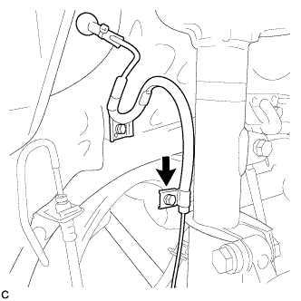
- Remove the bolt and separate the rear flexible hose from the rear shock absorber with coil spring.
| 6.
SEPARATE REAR SPEED SENSOR WIRE (for 2WD) |
|
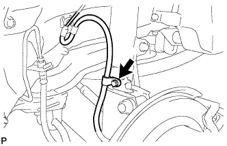
- Remove the bolt and separate the rear speed sensor from the rear shock absorber with coil spring.
| 7.
SEPARATE REAR SPEED SENSOR (for 4WD) |
|
- Remove the bolt and separate the rear speed sensor from the rear shock absorber with coil spring.
| 8.
SEPARATE REAR STABILIZER LINK ASSEMBLY (for 2WD) |
|
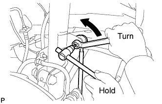
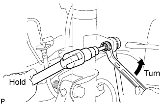
- Remove the nut and separate the rear stabilizer link assembly from the rear shock absorber with coil spring.
- HINT:
- If the ball joint turns together with the nut, use a hexagon wrench (5 mm) to hold the stud bolt.
| 9.
SEPARATE REAR STABILIZER LINK ASSEMBLY (for 4WD) |
|
- Remove the nut and separate the rear stabilizer link assembly from the rear shock absorber with coil spring.
- HINT:
- If the ball joint turns together with the nut, use a hexagon wrench (5 mm) to hold the stud bolt.
| 10.
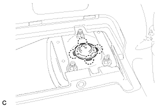
REMOVE REAR NO. 1 SUSPENSION SUPPORT COVER |
|
- Disengage the 4 claws and remove the rear No. 1 suspension support cover.
| 11.
REMOVE REAR SHOCK ABSORBER WITH COIL SPRING (for 2WD) |
|
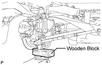
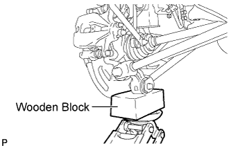
- Using a jack and wooden block, support the rear axle carrier sub-assembly.
- NOTICE:
- Do not deform the dust cover.
- HINT:
- Support the rear axle carrier sub-assembly until reinstallation of the rear shock absorber with coil spring is complete.
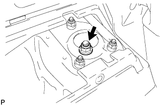
- Loosen the rear support to rear shock absorber nut.
- CAUTION:
- Do not remove the rear support to rear shock absorber nut.
- NOTICE:
- Loosen the nut only when the rear shock absorber with coil spring needs to be disassembled.
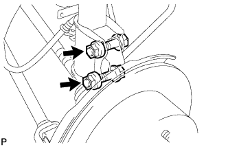
- Remove the 2 bolts and 2 nuts, and separate the rear shock absorber with coil spring from the rear axle carrier sub-assembly.
- NOTICE:
- When removing the nuts, keep the bolts from rotating.
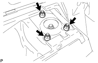
- Remove the 3 nuts and rear shock absorber with coil spring.
- NOTICE:
- Make sure that the rear speed sensor and rear flexible hose are disconnected from the rear shock absorber with coil spring.
| 12.
REMOVE REAR SHOCK ABSORBER WITH COIL SPRING (for 4WD) |
|
- Using a jack and wooden block, support the rear axle carrier sub-assembly.
- NOTICE:
- Do not deform the dust cover.
- HINT:
- Support the rear axle carrier sub-assembly until reinstallation of the rear shock absorber with coil spring is complete.
- Loosen the rear support to rear shock absorber nut.
- CAUTION:
- Do not remove the rear support to rear shock absorber nut.
- NOTICE:
- Loosen the nut only when the rear shock absorber with coil spring needs to be disassembled.
- Remove the 2 bolts and 2 nuts, and separate the rear shock absorber with coil spring from the rear axle carrier sub-assembly.
- NOTICE:
- When removing the nuts, keep the bolts from rotating.
- Remove the 3 nuts and rear shock absorber with coil spring.
- NOTICE:
- Make sure that the rear speed sensor and rear flexible hose are disconnected from the rear shock absorber with coil spring.
| 13.
REMOVE REAR SUPPORT TO REAR SHOCK ABSORBER NUT |
|
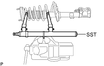
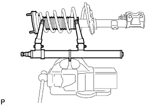
- Secure SST in a vise.
- SST
- 09727-30021
(09727-00010, 09727-00021, 09727-00031)
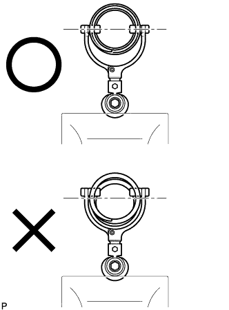
- Attach the arm of SST to the diameter of the rear coil spring.
- CAUTION:
- Make sure that the rear coil spring is installed so that the distance between the upper and lower hooks of SST is at the maximum.
- Make sure that the claws of the hooks are securely attached.
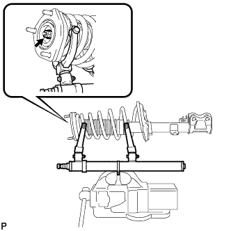
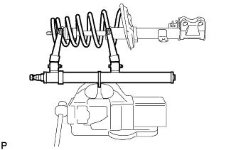
Using SST, compress the rear coil spring.
- CAUTION:
- If the rear coil spring bends during the compression, immediately stop the compression and reinstall SST.
- Do not compress the spring until the coil springs contact each other.
- Do not use an impact wrench. It will damage SST.
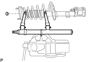
- Confirm that the rear coil spring becomes free and remove the rear support to rear shock absorber nut.
- CAUTION:
- Do not remove the rear support to rear shock absorber nut when the rear coil spring is not free.
| 14.
REMOVE REAR SUPPORT TO REAR SHOCK ABSORBER COLLAR |
|
- Remove the rear support to rear shock absorber collar from the rear shock absorber assembly.
| 15.
REMOVE REAR SUSPENSION SUPPORT ASSEMBLY |
|
- Remove the rear suspension support assembly from the rear shock absorber assembly.
| 16.
REMOVE REAR COIL SPRING |
|
- Remove the rear coil spring together with SST from the rear shock absorber assembly.
| 17.
REMOVE REAR NO. 1 SPRING BUMPER |
|
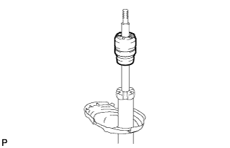
- Remove the rear No. 1 spring bumper from the rear shock absorber assembly.
| 18.
REMOVE REAR LOWER COIL SPRING INSULATOR |
|
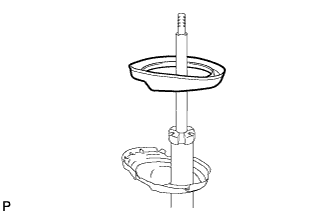
- Remove the rear lower coil spring insulator from the rear shock absorber assembly.