Home › SUSPENSION & AXLE › SUSPENSION › REAR LOWER ARM (for 4WD)REMOVAL
Removal / installation · Vehicles built from Jul 2010
Versions by build date: May 2007 – Jul 2008 Aug 2008 – Jun 2010 from Jul 2010
HINT:
The removal procedures for the LH and RH sides are different.
When removing RH side components, it is not necessary to follow the steps with (for LH Side).
When removing LH side components, it is not necessary to follow the steps with (for RH side).
1.
REMOVE REAR WHEEL (for RH Side)
2.
REMOVE REAR WHEELS (for LH Side)
3.
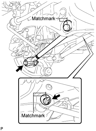
REMOVE REAR NO. 2 SUSPENSION ARM ASSEMBLY LH (for LH Side)
Put matchmarks on the adjust cams and the rear suspension member sub-assembly.
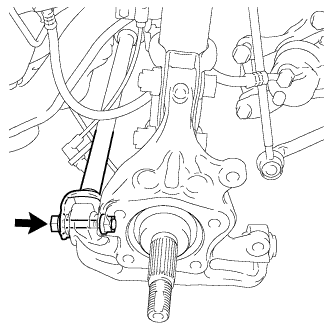
Remove the bolt and the nut, and separate the rear No. 2 suspension arm assembly LH from the rear axle carrier sub-assembly LH.
NOTICE:
Since a stopper nut is used, loosen the bolt.
Remove the nut, the No. 2 camber adjust cam, the rear suspension toe adjust cam sub-assembly, and the rear No. 2 suspension arm assembly LH.
HINT:
When removing the nut, keep the rear suspension toe adjust cam sub-assembly from rotating.
4.
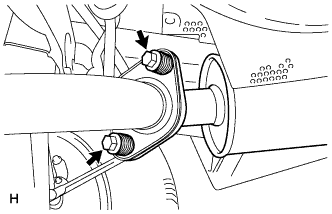
REMOVE TAIL EXHAUST PIPE ASSEMBLY
Remove the 2 bolts and 2 compression springs. Disconnect the exhaust pipe support and remove the tail exhaust pipe assembly.
Remove the gasket from the center exhaust pipe assembly.
5.
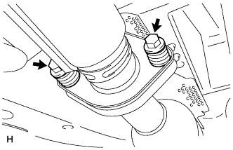
REMOVE CENTER EXHAUST PIPE ASSEMBLY
Remove the 2 bolts and 2 compression springs. Disconnect the 3 exhaust pipe supports and remove the center exhaust pipe assembly.
Remove the gasket from the No. 3 exhaust pipe sub-assembly.
6.
REMOVE REAR NO. 2 SUSPENSION ARM ASSEMBLY RH (for RH Side)
HINT:
Perform the same procedure as the LH side.
7.
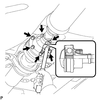
REMOVE PROPELLER WITH CENTER BEARING SHAFT ASSEMBLY (for LH Side)
Depress the brake pedal and hold it. Using a hexagon wrench (6 mm), loosen the cross groove joint set bolts 1/2 turn.
HINT:
Put a piece of cloth or equivalent into the inside of the universal joint cover so that the boot does not touch the inside of the universal joint cover.
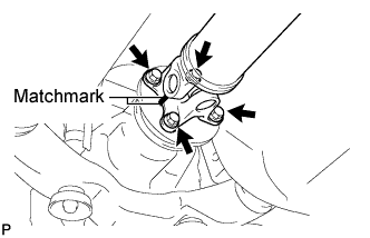
Place matchmarks on the rear propeller shaft and rear drive pinion flange sub-assembly. Remove the 4 nuts, 4 bolts and 4 washers.
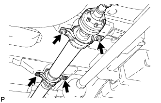
Remove the 4 bolts and 4 adjusting shims.
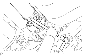
Using a brass bar and a hammer, remove the propeller shaft with center bearing shaft assembly.
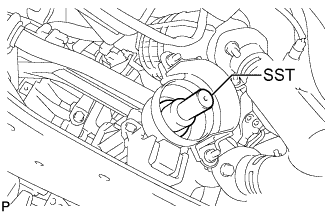
Insert SST into the transfer to prevent oil leakage.
SST
09325-20010
8.
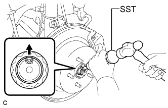
REMOVE REAR AXLE SHAFT NUT LH (for LH Side)
Using SST and a hammer, release the staked part of the rear axle shaft nut.
SST
09930-00010
NOTICE:
Loosen the staked part of the nut completely, otherwise the threads of the drive shaft may be damaged.
While applying the brakes, remove the rear axle shaft nut.
9.
REMOVE REAR AXLE SHAFT NUT RH (for LH Side)
HINT:
Perform the same procedure as the LH side.
10.
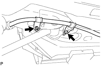
SEPARATE NO. 3 PARKING BRAKE CABLE ASSEMBLY (for LH Side)
Remove the bolt and the nut, and separate the No. 3 parking brake cable assembly.
11.
SEPARATE NO. 2 PARKING BRAKE CABLE ASSEMBLY
HINT:
Perform the same procedure as the No. 3 parking brake cable assembly.
12.
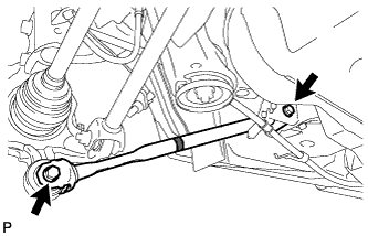
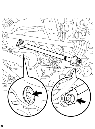
REMOVE REAR STRUT ROD ASSEMBLY LH (for LH Side)
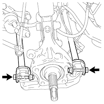
Remove the 2 bolts, the 2 nuts, and the rear strut rod assembly.
NOTICE:
Since stopper nuts are used, loosen the bolts.
13.
REMOVE REAR STRUT ROD ASSEMBLY RH
HINT:
Perform the same procedure as the LH side.
14.
REMOVE REAR NO. 1 SUSPENSION ARM ASSEMBLY RH (for RH Side)
Remove the bolt and the nut, and separate the rear No. 1 suspension arm assembly RH from the rear axle carrier sub-assembly RH.
NOTICE:
Since a stopper nut is used, loosen the bolt.
Remove the bolt, the nut, and the rear No. 1 suspension arm assembly RH from the rear suspension member sub-assembly.
NOTICE:
Since a stopper nut is used, loosen the bolt.
15.
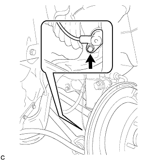
SEPARATE REAR SPEED SENSOR LH (for LH Side)
Remove the bolt and separate the rear speed sensor from the rear axle carrier sub-assembly.
NOTICE:
Keep the sensor tip and rear speed sensor installation hole free from foreign matter.
16.
SEPARATE REAR SPEED SENSOR RH (for LH Side)
HINT:
Perform the same procedure as the LH side.
17.
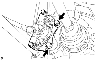
SEPARATE REAR DISC BRAKE CALIPER ASSEMBLY LH (for LH Side)
Remove the 2 bolts and separate the rear disc brake caliper assembly.
NOTICE:
Use wire or an equivalent tool to keep the brake caliper from hanging down by the flexible hose.
18.
SEPARATE REAR DISC BRAKE CALIPER ASSEMBLY RH (for LH Side)
HINT:
Perform the same procedure as the LH side.
19.
REMOVE REAR DISC (for LH Side)
Remove the rear disc from the rear axle hub and bearing assembly LH (Click here ).
Remove the rear disc from the rear axle hub and bearing assembly RH.
HINT:
Perform the same procedure as the LH side (Click here ).
20.
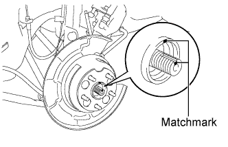
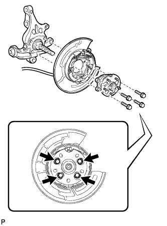
REMOVE REAR AXLE HUB AND BEARING ASSEMBLY LH (for LH Side)
Put matchmarks on the drive shaft and axle hub.
NOTICE:
Do not punch the marks.
Remove the 4 bolts and the rear axle hub and bearing assembly.
NOTICE:
Do not rotate the drive shaft with the rear axle hub and bearing assembly removed.
Use wire or an equivalent tool to keep the parking brake assembly from hanging down by the parking brake cable assembly.
21.
REMOVE REAR AXLE HUB AND BEARING ASSEMBLY RH (for LH Side)
HINT:
Perform the same procedure as the LH side.
22.
REMOVE REAR AXLE CARRIER SUB-ASSEMBLY LH (for LH Side)
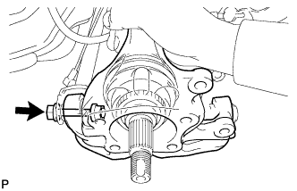
Loosen the bolt.
NOTICE:
Since a stopper nut is used, loosen the bolt.
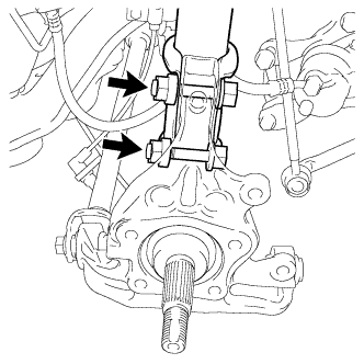
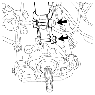
Remove the 2 bolts and 2 nuts, and separate the rear shock absorber with coil spring from the rear axle carrier sub-assembly LH.
NOTICE:
Be careful not to damage the outboard joint boot.
Be careful not to damage the speed sensor rotor.
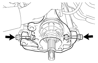
Remove the bolt, the nut, and the rear axle carrier sub-assembly LH.
NOTICE:
Be careful not to damage the outboard joint boot.
Be careful not to damage the speed sensor rotor.
HINT:
Use a rope or equivalent to hang the rear drive shaft assembly.
23.
REMOVE REAR AXLE CARRIER SUB-ASSEMBLY RH (for LH Side)
Loosen the 2 bolts.
NOTICE:
Since stopper nuts are used, loosen the bolts.
Remove the 2 bolts and 2 nuts, and separate the rear shock absorber with coil spring from the rear axle carrier sub-assembly RH.
NOTICE:
Be careful not to damage the outboard joint boot.
Be careful not to damage the speed sensor rotor.
Remove the 2 bolts, the 2 nuts, and the rear axle carrier sub-assembly RH.
NOTICE:
Be careful not to damage the outboard joint boot.
Be careful not to damage the speed sensor rotor.
HINT:
Use a rope or equivalent to hang the rear drive shaft assembly.
24.
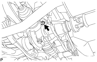
REMOVE REAR DIFFERENTIAL FILLER PLUG (for LH Side)
Using a hexagon wrench (10 mm), remove the rear differential filler plug and rear differential filler plug gasket.
25.
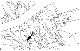
REMOVE REAR DIFFERENTIAL DRAIN PLUG (for LH Side)
Using a hexagon wrench (10 mm), remove the rear differential drain plug and rear differential drain plug gasket, and drain the oil.
26.
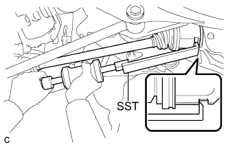
REMOVE REAR DRIVE SHAFT ASSEMBLY LH (for LH Side)
Using SST, remove the rear drive shaft assembly as shown in the illustration.
SST
09520-01010
NOTICE:
Remove the rear drive shaft assembly while keeping it level.
27.
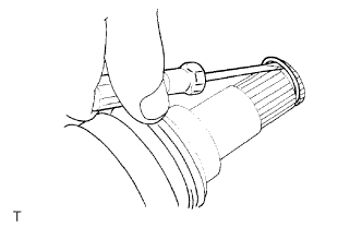
REMOVE REAR DRIVE SHAFT SNAP RING LH (for LH Side)
Using a screwdriver, remove the rear drive shaft snap ring.
28.
REMOVE REAR DRIVE SHAFT ASSEMBLY RH (for LH Side)
HINT:
Perform the same procedure as the LH side.
29.
REMOVE REAR DRIVE SHAFT SNAP RING RH (for LH Side)
HINT:
Perform the same procedure as the LH side.
30.
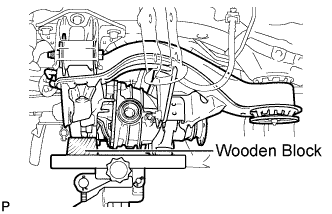
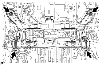
REMOVE REAR SUSPENSION MEMBER (for LH Side)
Support the rear suspension member with a jack using a wooden block.
HINT:
Use a properly sized wooden block to keep the jack and suspension member level.
Remove the 4 nuts, 2 bolts and 2 rear lower suspension member stopper retainers. Lower the rear suspension member.
Remove the 2 rear upper suspension member stoppers.
31.
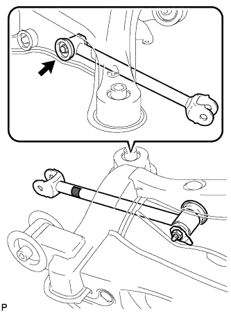
REMOVE REAR NO. 1 SUSPENSION ARM ASSEMBLY LH (for LH Side)
Remove the bolt, the nut, and the rear No. 1 suspension arm assembly LH from the rear suspension member sub-assembly.
NOTICE:
Since a stopper nut is used, loosen the bolt.