Door LOCK Position Circuit
Circuit diagnosis · Vehicles built Aug 2008 – Jun 2010
Versions by build date: May 2007 – Jul 2008 Aug 2008 – Jun 2010 from Jul 2010
DESCRIPTION
The main body ECU receives each door lock position switch signal to control the illuminated entry system.WIRING DIAGRAM
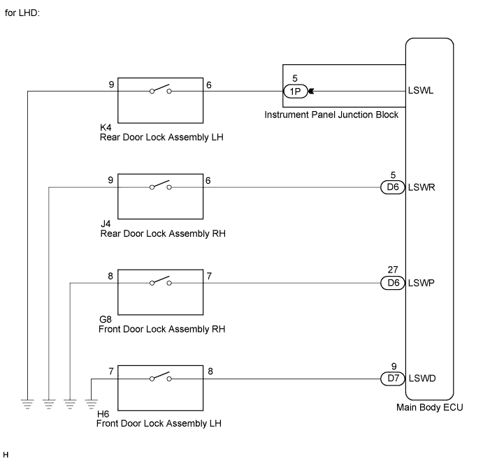

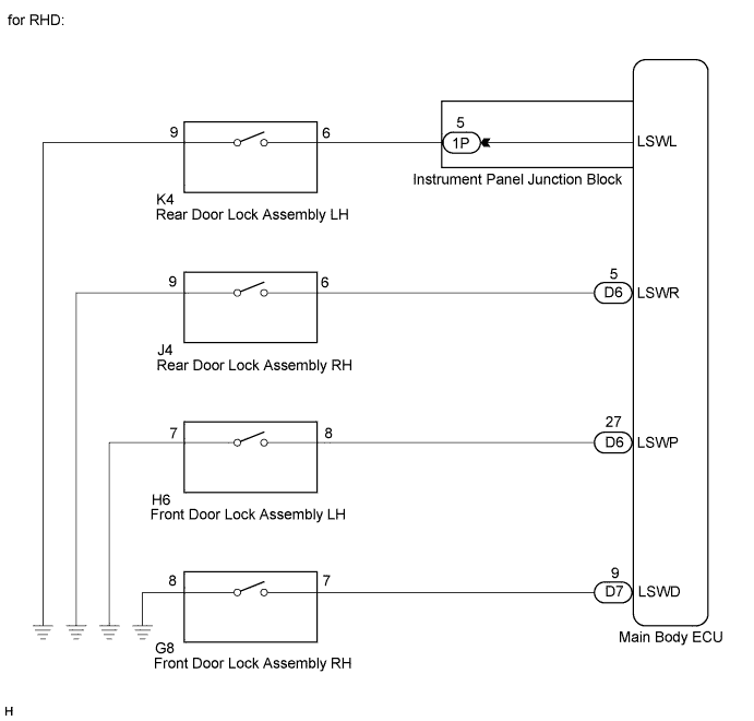
INSPECTION PROCEDURE
| 1. READ VALUE USING INTELLIGENT TESTER |

Connect the intelligent tester to the DLC3.
Turn the ignition switch on (IG).
Turn the intelligent tester on.
Select the following menu items: Body Electrical / Main Body / Data List.
Read the display on the intelligent tester.
Main Body: Tester Display
Measurement Item/Range
Normal Condition
Diagnostic Note
D-Door Lock Pos SW
Driver side door lock position switch signal / ON or OFF
ON: Driver side door unlocked
OFF: Driver side door locked
-
P-Door Lock Pos SW
Front passenger side door lock position switch signal / ON or OFF
ON: Front passenger side door unlocked
OFF: Front passenger side locked
-
RL-Door Lock Pos SW
Rear door lock position switch LH signal / ON or OFF
ON: Rear door LH unlocked
OFF: Rear door LH locked
-
RR-Door Lock Pos SW
Rear door lock position switch RH signal / ON or OFF
ON: Rear door RH unlocked
OFF: Rear door RH locked
-
- OK:
- Normal conditions listed above are displayed.
- HINT:
- If the normal condition listed above are not displayed, perform the trouble shooting of the power door lock control system.
|
|
||||

| OK | ||
 |
||
| ||