TERMINALS OF ECU
System information · Vehicles built from Jul 2010
Versions by build date: May 2007 – Jun 2010 from Jul 2010
| CLOCK ASSEMBLY (w/o Multi-information Display) |
- HINT:
- Measure the voltage with the connector still connected.


| Terminal No. (Symbols) |
Wiring Color |
Terminal Description |
Condition |
Specified Condition |
| E20-1 (B) - Body ground |
Y - Body ground |
Battery |
Always |
11 to 14 V |
| E20-2 (E) - Body ground |
BR - Body ground |
Ground |
Always |
Below 1 V |
| E20-4 (ACC) - Body ground |
L - Body ground |
Ignition switch signal (Accessory) |
Ignition switch off |
Below 1 V |
| Ignition switch on (ACC) |
11 to 14 V |
Waveform (Reference): Using oscilloscope: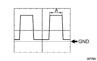
Item
Condition
Tool setting
2 V/DIV., 1 ms./DIV.
Vehicle condition
Ignition switch on (IG), light control switch TAIL/HEAD
- HINT:
- Duty ratio changes as the illumination becomes darker (the period "A" shown in the illustration becomes longer).
| CLOCK ASSEMBLY (w/ Multi-information Display) |
- HINT:
- Measure the voltage with the connector still connected.

| Terminal No. (Symbols) |
Wiring Color |
Terminal Description |
Condition |
Specified Condition |
| E9-1 (IG) - Body ground |
P - Body ground |
Ignition switch signal |
Ignition switch off |
Below 1 V |
| Ignition switch on (IG) |
11 to 14 V |
|||
| E9-5 (GND) - Body ground |
W-B - Body ground |
Ground |
Always |
Below 1 V |
| E9-6 (+B) - Body ground |
Y - Body ground |
Battery |
Always |
11 to 14 V |
| E9-9 (CLK) - Body ground |
R - Body ground |
Multi-information display signal |
Ignition switch on (IG) |
Pulse generation |
| E9-10 (DATA) - Body ground |
Y - Body ground |
Multi-information display signal |
Ignition switch on (IG) |
Pulse generation |
| E9-11 (SYNC) - Body ground |
L - Body ground |
Multi-information display signal |
Ignition switch on (IG) |
Pulse generation |
| E9-16 (SGND) - Body ground |
BR - Body ground |
Ground (Signal Ground) |
Always |
Always |