2007-2013 Highlander Kluger · Service Manual ENGINE

REMOVAL

Removal / installation · Vehicles built Aug 2008 – Jun 2010

Versions by build date: May 2007 – Jul 2008 Aug 2008 – Jun 2010 Jul 2010 – Jul 2013 from Aug 2013


1. RECOVER REFRIGERANT FROM REFRIGERATION SYSTEM
  1. Start the engine.

  1. Turn the A/C switch on.

  1. Operate the cooler compressor at an engine speed of approximately 1000 rpm for 5 to 6 minutes to circulate the refrigerant. This causes most of the compressor oil from the various components of the A/C system to collect in the A/C compressor.

  1. Stop the engine.

  1. Recover the refrigerant from the A/C system using a refrigerant recovery unit.


2. REMOVE V-BANK COVER SUB-ASSEMBLY

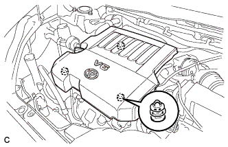
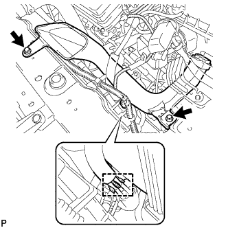
  1. A162365
    Hold the front of the V-bank cover sub-assembly and raise it to disengage the 2 clips on the front of the V-bank cover sub-assembly. Continue rising the V-bank cover sub-assembly to disengage the clip on the rear of the V-bank cover sub-assembly and remove the V-bank cover sub-assembly.

    NOTICE:
    Attempting to disengage both front and rear clips at the same time may cause the V-bank cover sub-assembly to break.


3. REMOVE ENGINE UNDER COVER ASSEMBLY

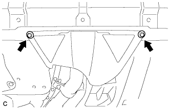
  1. A171849
    Remove the 2 bolts and engine under cover assembly RR.

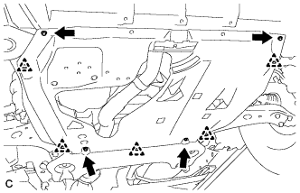
  1. A171850
    Remove the 2 bolts, 2 screws, 5 clips and engine under cover assembly.


4. REMOVE NO. 1 ENGINE UNDER COVER

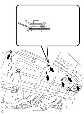
  1. A171855
    Remove the 6 bolts, 2 clips and No. 1 engine under cover.


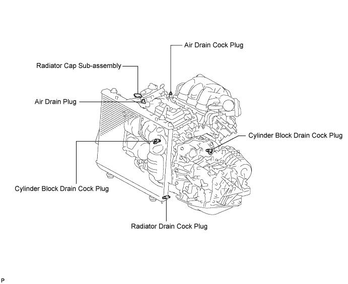
5. DRAIN ENGINE COOLANT

  1. Loosen the radiator drain cock plug.

    A169414E01

    HINT:
    Collect the coolant in a container and dispose of it according to the regulations in your area.

  1. Remove the radiator cap sub-assembly from the radiator assembly.

    NOTICE:
    Do not remove the radiator cap sub-assembly while the engine and radiator are still hot. Pressurized, hot engine coolant and steam may be released and cause serious burns.

  1. Loosen the 2 cylinder block drain cock plugs.


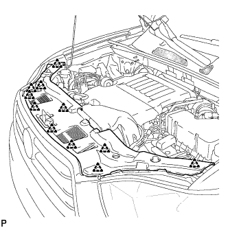
6. REMOVE COOL AIR INTAKE DUCT SEAL

  1. A170196
    Remove the 11 clips and cool air intake duct seal.


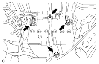
7. REMOVE BATTERY

CAUTION:
Wait at least 90 seconds after disconnecting the cable from the negative (-) battery terminal to prevent airbag and seat belt pretensioner activation.

NOTICE:
When disconnecting the cable, some systems need to be initialized after the cable is reconnected (Click here).

  1. A175880
    Loosen the nut, and disconnect the negative battery terminal.

  1. Loosen the nut, and disconnect the positive battery terminal.

  1. Loosen the nut, and remove the bolt and battery clamp.

  1. Remove the battery and battery tray.


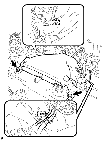
8. REMOVE NO. 2 AIR CLEANER INLET

  1. A170453
    Disconnect the 2 vacuum switching valve clamps.

  1. Disconnect the 2 vacuum hoses.

  1. Remove the 2 bolts and No. 2 air cleaner inlet.


9. REMOVE NO. 1 AIR CLEANER INLET

  1. A170454
    Disconnect the 2 vacuum hoses, and remove the 2 bolts and No. 1 air cleaner inlet.


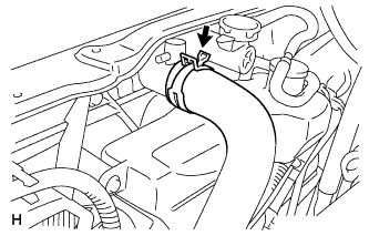
10. DISCONNECT NO. 1 RADIATOR HOSE

  1. A169427
    Disconnect the No. 1 radiator hose from the radiator.


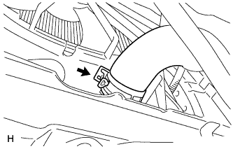
11. DISCONNECT NO. 2 RADIATOR HOSE

  1. A169428
    Disconnect the No. 2 radiator hose from the radiator.


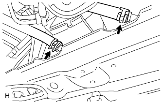
12. DISCONNECT OIL COOLER HOSE

  1. A169429
    Disconnect the oil cooler hoses from the radiator.


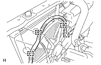
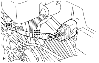
13. DISCONNECT COOLING FAN ECU CONNECTOR

  1. A169435
    Detach the wire harness clamps from the fan shroud LH side.

  1. A169436
    Detach the wire harness clamps from the fan shroud RH side and disconnect the cooling fan ECU connector.


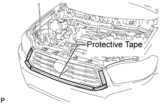
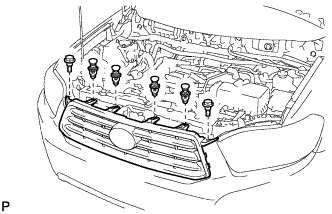
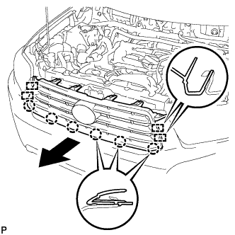
14. REMOVE RADIATOR GRILLE

  1. B172749E01
    Put protective tape around the radiator grille.

  1. B172746
    Remove the 2 bolts and 4 clips.

  1. B172747
    Disengage the 6 claws and 4 guides, and remove the radiator grille.


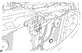
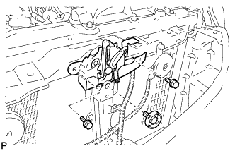
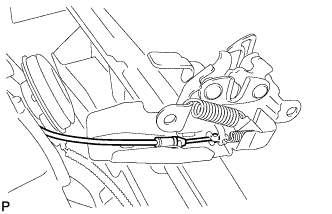
15. REMOVE HOOD LOCK ASSEMBLY (w/o Engine Hood Courtesy Switch)

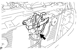
  1. B174188
    Remove the hood lock nut cap.

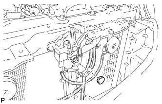
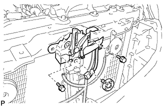
  1. B174189
    Remove the 3 bolts.

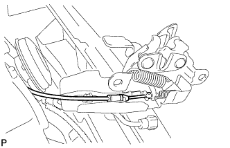
  1. B174190
    Disconnect the hood lock control cable and remove the hood lock assembly.


16. REMOVE HOOD LOCK ASSEMBLY (w/ Engine Hood Courtesy Switch)

  1. B174191
    Disconnect the connector.

  1. B174192
    Remove the hood lock nut cap.

  1. B174193
    Remove the 3 bolts.

  1. B174194
    Disconnect the hood lock control cable and remove the hood lock assembly.


17. REMOVE UPPER RADIATOR SUPPORT SUB-ASSEMBLY (for LHD)

  1. A169432
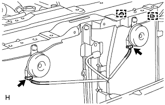
    Disconnect the low pitched horn and high pitched horn connectors.

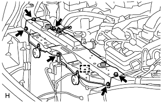
  1. A169469
    Detach the hood lock control cable clamp and remove the 6 bolts and upper radiator support sub-assembly.


18. REMOVE UPPER RADIATOR SUPPORT SUB-ASSEMBLY (for RHD)

  1. A169432
    Disconnect the low pitched horn and high pitched horn connectors.

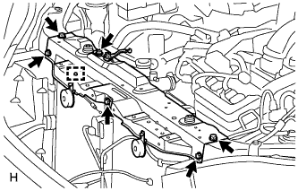
  1. A169470
    Detach the hood lock control cable clamp and remove the 6 bolts and upper radiator support sub-assembly.


19. SEPARATE COOLER CONDENSER ASSEMBLY

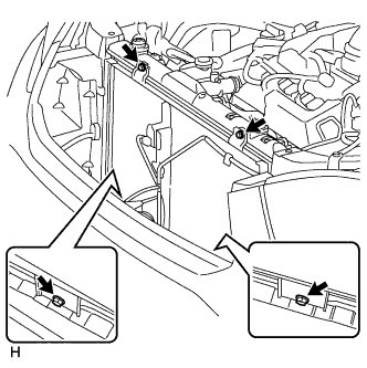
  1. A169439
    Remove the 4 bolts and move the cooler condenser assembly to remove the radiator assembly and fan assembly with motor.


20. REMOVE RADIATOR ASSEMBLY AND FAN ASSEMBLY WITH MOTOR

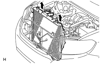
  1. A169440
    Remove the radiator assembly and fan assembly with motor.


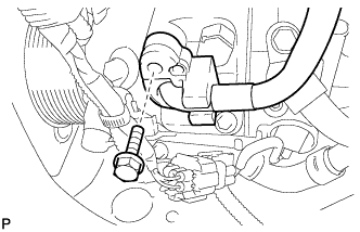
21. DISCONNECT DISCHARGE HOSE SUB-ASSEMBLY

  1. E150345
    Remove the bolt and disconnect the discharge hose sub-assembly from the compressor and magnetic clutch.

  1. Remove the O-ring from the discharge hose sub-assembly.

    NOTICE:
    Seal the openings of the disconnected parts using vinyl tape to prevent entry of moisture and foreign matter.


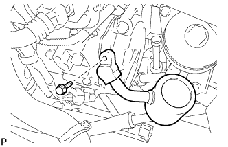
22. DISCONNECT SUCTION HOSE SUB-ASSEMBLY

  1. E150346
    Remove the bolt and disconnect the suction hose sub-assembly from the compressor and magnetic clutch.

  1. Remove the O-ring from the suction hose sub-assembly.

    NOTICE:
    Seal the openings of the disconnected parts using vinyl tape to prevent entry of moisture and foreign matter.


23. REMOVE COMPRESSOR AND MAGNETIC CLUTCH

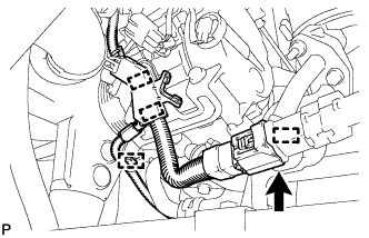
  1. E150347
    Disengage the clamp.

  1. Disconnect the connector.

  1. E150348
    Disengage each clamp.

  1. Disconnect the connector.

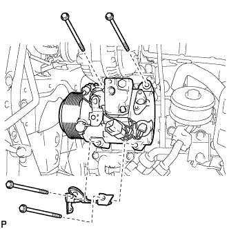
  1. E151053
    Remove the 4 bolts and the compressor and magnetic clutch.


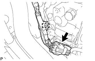
24. REMOVE CRANKSHAFT POSITION SENSOR

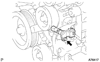
  1. A076417
    Disconnect the crankshaft position sensor connector.

  1. Remove the bolt and crankshaft position sensor.

← REMOVAL (May 2007 – Jul 2008)REMOVAL (Jul 2010 – Jul 2013) →