TERMINALS OF ECU
System information · Vehicles built from May 2007
| CHECK POWER WINDOW ECU (DRIVER SIDE) |
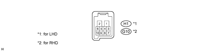

Disconnect the H1 switch connector (LHD).
Disconnect the G10 switch connector (RHD).
Measure the voltage and resistance according to the value(s) in the table below.
- Standard resistance:
Tester Connection
Wiring Color
Terminal Description
Condition
Specified Condition
H1-1 (E) - Body ground (*1)
W-B - Body ground
Ground
Always
Below 1 Ω
G10-1 (E) - Body ground (*2)
- HINT:
- *1: for LHD
- *2: for RHD
- Standard voltage:
Tester Connection
Wiring Color
Terminal Description
Condition
Specified Condition
H1-2 (B) - Body ground (*1)
B - Body ground (*1)
Power supply
Always
11 to 14 V
G10-2 (B) - Body ground (*2)
SB - Body ground (*2)
- HINT:
- *1: for LHD
- *2: for RHD
| CHECK POWER WINDOW MASTER SWITCH |
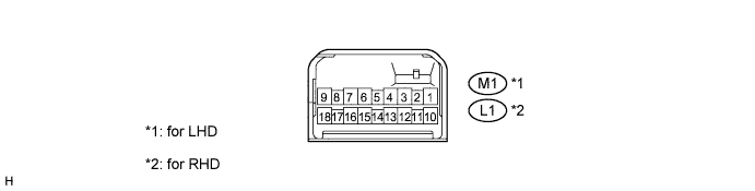
Disconnect the M1 switch connector (LHD).
Disconnect the L1 switch connector (RHD).
Measure the voltage and resistance of each terminal according to the value(s) in the table below.
- Standard resistance:
for LHD: Tester Connection
Wiring Color
Terminal Description
Condition
Specified Condition
M1-1 (E) - Body ground
W-B - Body ground
Ground
Always
Below 1 Ω
for RHD: Tester Connection
Wiring Color
Terminal Description
Condition
Specified Condition
L1-9 (E) - Body ground
W-B - Body ground
Ground
Always
Below 1 Ω
- Standard voltage:
for LHD: Tester Connection
Wiring Color
Terminal Description
Condition
Specified Condition
M1-6 (B) - M1-1 (E)
B - W-B
Power supply
Ignition switch on (IG)
11 to 14 V
Ignition switch off
Below 1 V
for RHD: Tester Connection
Wiring Color
Terminal Description
Condition
Specified Condition
L1-6 (B) - L1-9 (E)
B - W-B
Power supply
Ignition switch on (IG)
11 to 14 V
Ignition switch off
Below 1 V
Reconnect the M1 and L1 switch connectors.
Measure the voltage according to the value(s) in the table below.
- Standard voltage:
for LHD: Tester Connection
Wiring Color
Terminal Description
Condition
Specified Condition
M1-16 (U) - M1-1 (E)
W - W-B
Power window motor UP output
Ignition switch on (IG), front passenger side power window switch OFF
Below 1 V
Power window switch UP (Manual operation)
11 to 14 V
M1-15 (D) - M1-1 (E)
SB - W-B
Power window motor DOWN output
Ignition switch on (IG), front passenger side power window switch OFF
Below 1 V
Power window switch DOWN (Manual operation)
11 to 14 V
M1-12 (U) - M1-1 (E)
L - W-B
Power window motor UP output
Ignition switch on (IG), rear LH side power window switch OFF
Below 1 V
Power window switch UP (Manual operation)
11 to 14 V
M1-13 (D) - M1-1 (E)
O - W-B
Power window motor DOWN output
Ignition switch on (IG), rear LH side power window switch OFF
Below 1 V
Power window switch UP (Manual operation)
11 to 14 V
M1-10 (U) - M1-1 (E)
Y - W-B
Power window motor UP output
Ignition switch on (IG), rear RH side power window switch OFF
Below 1 V
Power window switch UP (Manual operation)
11 to 14 V
M1-18 (D) - M1-1 (E)
LG - W-B
Power window motor DOWN output
Ignition switch on (IG), rear RH side power window switch OFF
Below 1 V
Power window switch UP (Manual operation)
11 to 14 V
for RHD: Tester Connection
Wiring Color
Terminal Description
Condition
Specified Condition
L1-12 (U) - L1-9 (E)
W - W-B
Power window motor UP output
Ignition switch on (IG), front passenger side power window switch OFF
Below 1 V
Power window switch UP (Manual operation)
11 to 14 V
L1-13 (D) - L1-9 (E)
SB - W-B
Power window motor DOWN output
Ignition switch on (IG), front passenger side power window switch OFF
Below 1 V
Power window switch DOWN (Manual operation)
11 to 14 V
L1-18 (U) - L1-9 (E)
L - W-B
Power window motor UP output
Ignition switch on (IG), rear LH side power window switch OFF
Below 1 V
Power window switch UP (Manual operation)
11 to 14 V
L1-10 (D) - L1-9 (E)
O - W-B
Power window motor DOWN output
Ignition switch on (IG), rear LH side power window switch OFF
Below 1 V
Power window switch UP (Manual operation)
11 to 14 V
L1-16 (U) - L1-9 (E)
Y - W-B
Power window motor UP output
Ignition switch on (IG), rear RH side power window switch OFF
Below 1 V
Power window switch UP (Manual operation)
11 to 14 V
L1-15 (D) - L1-9 (E)
LG - W-B
Power window motor DOWN output
Ignition switch on (IG), rear RH side power window switch OFF
Below 1 V
Power window switch UP (Manual operation)
11 to 14 V
| CHECK POWER WINDOW SWITCH (FRONT PASSENGER) |
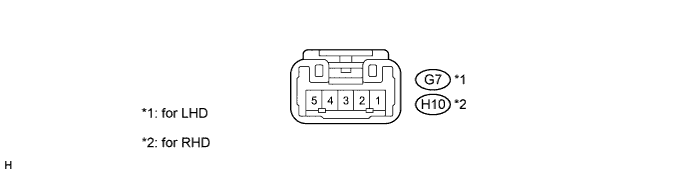
Disconnect the G7 switch connector (LHD).
Disconnect the H10 switch connector (RHD).
Measure the voltage according to the value(s) in the table below.
- Standard voltage:
Tester Connection
Wiring Color
Terminal Description
Condition
Specified Condition
G7-3 (B) - Body ground (*1)
O - Body ground
Power supply
Ignition switch on (IG)
11 to 14 V
H10-3 (B) - Body ground (*2)
Ignition switch off
Below 1 V
- HINT:
- *1: for LHD
- *2: for RHD
Reconnect the G7 switch connector (LHD).
Reconnect the H10 switch connector (RHD).
Measure the voltage according to the value(s) in the table below.
- Standard voltage:
Tester Connection
Wiring Color
Terminal Description
Condition
Specified Condition
G7-4 (U) - Body ground (*1)
G - Body ground
Power window motor UP output
Ignition switch on (IG), front passenger side power window switch OFF
Below 1 V
H10-4 (U) - Body ground (*2)
Power window switch UP (Manual operation)
11 to 14 V
G7-1 (D) - Body ground (*1)
Y - Body ground
Power window motor DOWN output
Ignition switch on (IG), front passenger side power window switch OFF
Below 1 V
H10-1 (D) - Body ground (*2)
Power window switch DOWN (Manual operation)
11 to 14 V
- HINT:
- *1: for LHD
- *2: for RHD
| CHECK POWER WINDOW SWITCH (REAR LH) |

Disconnect the K2 switch connector.
Measure the voltage according to the value(s) in the table below.
- Standard voltage:
Tester Connection
Wiring Color
Terminal Description
Condition
Specified Condition
K2-3 (B) - Body ground
G - Body ground
Power supply
Ignition switch on (IG)
11 to 14 V
Ignition switch off
Below 1 V
Reconnect the K2 switch connector.
Measure the voltage according to the value(s) in the table below.
- Standard voltage:
Tester Connection
Wiring Color
Terminal Description
Condition
Specified Condition
K2-4 (U) - Body ground
V - Body ground
Power window motor UP output
Ignition switch on (IG), rear LH side power window switch OFF
Below 1 V
Power window switch UP (Manual operation)
11 to 14 V
K2-1 (D) - Body ground
SB - Body ground
Power window motor DOWN output
Ignition switch on (IG), rear LH side power window switch OFF
Below 1 V
Power window switch DOWN (Manual operation)
11 to 14 V
| CHECK POWER WINDOW SWITCH (REAR RH) |

Disconnect the J2 switch connector.
Measure the voltage according to the value(s) in the table below.
- Standard voltage:
Tester Connection
Wiring Color
Terminal Description
Condition
Specified Condition
J2-3 (B) - Body ground
SB - Body ground
Power supply
Ignition switch on (IG)
11 to 14 V
Ignition switch off
Below 1 V
Reconnect the J2 switch connector.
Measure the voltage according to the value(s) in the table below.
- Standard voltage:
Tester Connection
Wiring Color
Terminal Description
Condition
Specified Condition
J2-4 (U) - Body ground
V - Body ground
Power window motor UP output
Ignition switch on (IG), rear RH side power window switch OFF
Below 1 V
Power window switch UP (Manual operation)
11 to 14 V
J2-1 (D) - Body ground
R - Body ground
Power window motor DOWN output
Ignition switch on (IG), rear RH side power window switch OFF
Below 1 V
Power window switch DOWN (Manual operation)
11 to 14 V