INSTALLATION
Removal / installation · Vehicles built from Jul 2010
Versions by build date: May 2007 – Jul 2008 Aug 2008 – Jun 2010 from Jul 2010
| 1. INSTALL MANUAL VALVE |

Install the manual valve to the valve body assembly.
| 2. INSTALL TRANSMISSION VALVE BODY ASSEMBLY |
Install the spring and check ball body.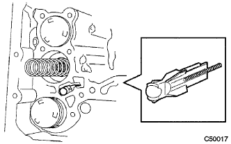

Align the groove of the manual valve with the pin of the lever.
Install the 17 bolts.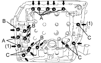
- Torque:
- 11 N*m{ 110 kgf*cm , 8 ft.*lbf }
- NOTICE:
- Push the valve body against the accumulator piston springs and check ball body to install the valve body.
- First, temporarily tighten the bolts marked (1) in the illustration because they are positioning bolts.
- Push the valve body against the accumulator piston springs and check ball body to install the valve body.
- Bolt length:
- Bolt A:
- 25 mm (0.98 in.)
- Bolt B:
- 57 mm (2.24 in.)
- Bolt C:
- 41 mm (1.61 in.)
| 3. INSTALL VALVE BODY OIL STRAINER ASSEMBLY |
Coat a new O-ring with ATF.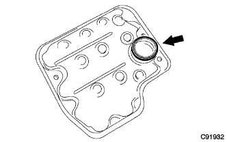
Install the O-ring to the oil strainer.
Install the oil strainer with the 3 bolts.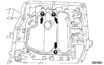
- Torque:
- 11 N*m{ 110 kgf*cm , 8 ft.*lbf }
| 4. INSTALL TRANSMISSION WIRE |
Coat a new O-ring with ATF.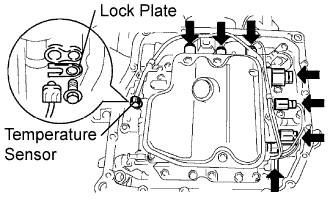
Install the ATF temperature sensor with the lock plate and bolt.
- Torque:
- 6.6 N*m{ 67 kgf*cm , 58 in.*lbf }
Connect the 7 shift solenoid valve connectors.
| 5. INSTALL AUTOMATIC TRANSAXLE OIL PAN SUB-ASSEMBLY |
Install the 2 magnets in the oil pan.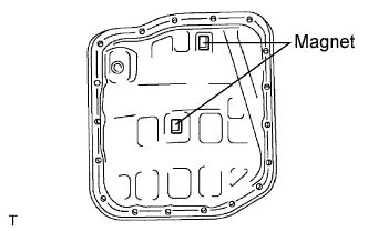
Apply adhesive to the 18 bolts.
- Adhesive:
- Toyota Genuine Adhesive 1344, Three Bond 1344 or equivalent
Install the oil pan and a new gasket to the transaxle case with the 18 bolts.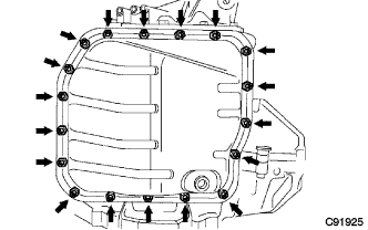
- Torque:
- 7.8 N*m{ 80 kgf*cm , 69 in.*lbf }
- NOTICE:
- Apply adhesive to the bolts and tighten them within 10 minutes of application.
| 6. INSTALL AUTOMATIC TRANSAXLE ASSEMBLY |
- HINT:
- (Click here)
| 7. CONNECT CABLE TO NEGATIVE BATTERY TERMINAL |
- NOTICE:
- When disconnecting the cable, some systems need to be initialized after the cable is reconnected (Click here).
| 8. ADD AUTOMATIC TRANSAXLE FLUID |
| 9. INSPECT AUTOMATIC TRANSAXLE FLUID |
- HINT:
- Drive the vehicle so that the engine and transaxle are at normal operating temperature.
- Fluid temperature:
- 70 to 80°C (158 to 176°F)
Park the vehicle on a level surface and set the parking brake.
With the engine idling and the brake pedal depressed, move the shift lever to all positions from P to S1 and return to the P position.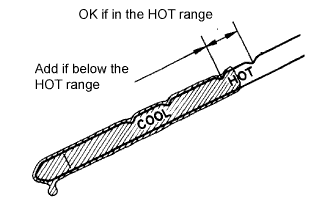
Take out the dipstick and wipe it clean.
Put the dipstick back all the way.
Take out the dipstick again and check that the fluid level is within the HOT range.
If the fluid level is below the HOT range, add new fluid and recheck the fluid level.
If the fluid level exceeds the HOT range, drain the fluid once, add the proper amount of new fluid and recheck the fluid level.
If there are leaks, it is necessary to repair or replace O-rings, FIPGs, oil seals, plugs and/or other parts.
| 10. INSPECT FOR TRANSAXLE FLUID LEAK |
| 11. INSTALL NO. 2 ENGINE UNDER COVER |
Install the No. 2 engine under cover with the 2 bolts.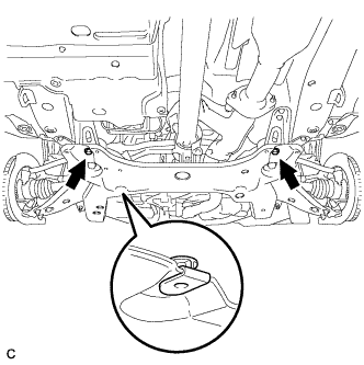
| 12. INSTALL NO. 1 ENGINE UNDER COVER |
Install the No. 1 engine under cover with the 6 bolts and 2 clips.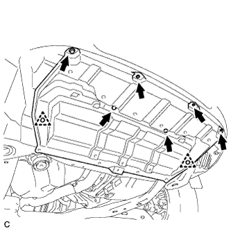
| 13. INSTALL ENGINE UNDER COVER ASSEMBLY |
Install the engine under cover assembly with the 2 bolts, 2 screws and 5 clips.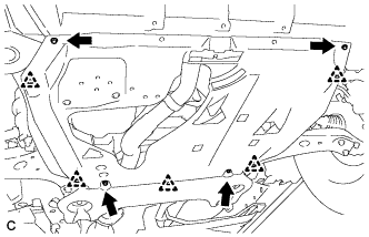
Install the engine under cover assembly RR with the 2 bolts.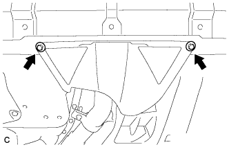
| 14. RESET MEMORY |
- HINT:
- (Click here)