INSTALLATION
Removal / installation · Vehicles built from Jul 2010
Versions by build date: May 2007 – Jul 2008 Aug 2008 – Jun 2010 from Jul 2010
| 1.
INSTALL QUICK HEATER ASSEMBLY |
 |
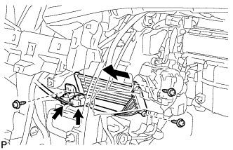
- Install the quick heater assembly with the 3 screws as shown in the illustration.
Connect the 2 connectors.
| 2.
INSTALL NO. 3 AIR DUCT SUB-ASSEMBLY |
|
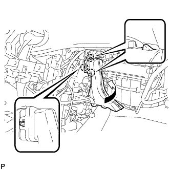
- Engage the 3 claws and install the No. 3 air duct sub-assembly as shown in the illustration.
| 3.
INSTALL FRONT NO. 2 CONSOLE BOX INSERT
|
|
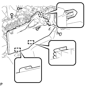
- Engage the claw and 2 guides.
Install the front No. 2 console box insert with the 3 screws <E> and clip.
| 4.
INSTALL CONSOLE BOX ASSEMBLY
|
|
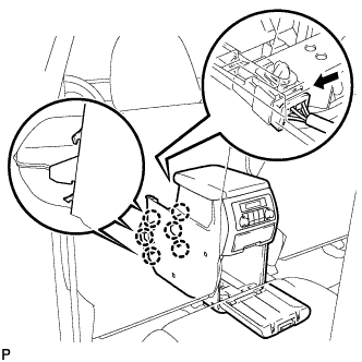
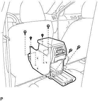
- Engage the 6 claws.
Connect the connector.
- Install the console box assembly with the 4 bolts and 2 screws.
| 5.
INSTALL LOWER REAR CONSOLE BOX
|
|
Install the lower rear console box.
| 6.
INSTALL UPPER CONSOLE PANEL SUB-ASSEMBLY
|
|
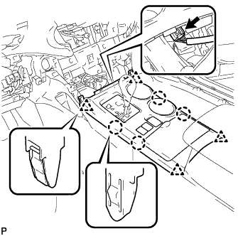
- Connect the connector.
Engage the 4 claws and 4 clips, and install the upper console panel sub-assembly.
| 7.
INSTALL LOWER INSTRUMENT PANEL SUB-ASSEMBLY
|
|
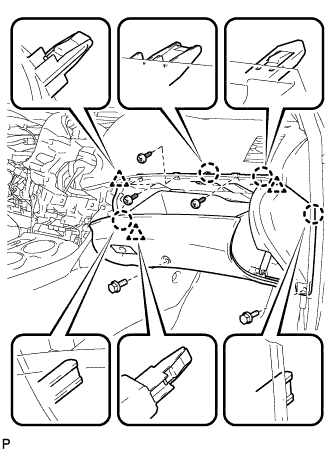
Connect each connector and clamp.
- Engage the 4 claws and 3 clips.
Install the lower instrument panel sub-assembly with the 2 bolts <B> and 3 screws <E>.
| 8.
INSTALL NO. 2 INSTRUMENT PANEL UNDER COVER SUB-ASSEMBLY
|
|
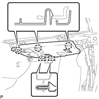
- Engage the 2 guides.
Engage the 3 claws and install the No. 2 instrument panel under cover sub-assembly.
| 9.
INSTALL COWL SIDE TRIM SUB-ASSEMBLY RH
|
|
- HINT:
- Use the same procedure for the RH side and the LH side.
| 10.
INSTALL FRONT DOOR SCUFF PLATE RH
|
|
- HINT:
- Use the same procedure for the RH side and the LH side.
| 11.
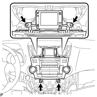
INSTALL RADIO RECEIVER ASSEMBLY WITH BRACKET (w/o Navigation System)
|
|
Connect each connector.
- Engage the 4 clips.
- Install the radio receiver assembly with bracket with the 4 bolts.
| 12.
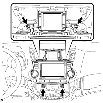
INSTALL NAVIGATION RECEIVER ASSEMBLY WITH BRACKET (w/ Navigation System)
|
|
Connect each connector.
- Engage the 4 clips.
- Install the navigation receiver assembly with bracket with the 4 bolts.
| 13.
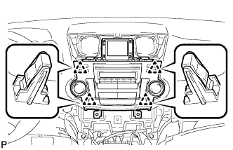
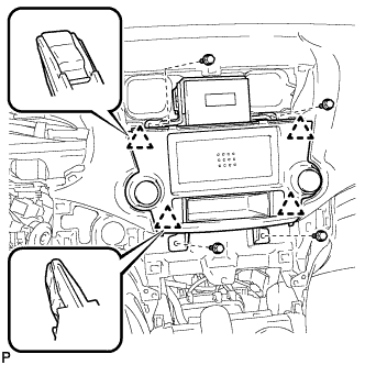
INSTALL INTEGRATION CONTROL AND PANEL ASSEMBLY WITH BRACKET (w/o Radio Receiver)
|
|
Connect each connector.
- Engage the 4 clips.
Install the integration control and panel assembly with bracket with the 4 bolts <D>.
| 14.
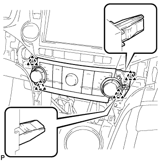
INSTALL HEATER CONTROL AND ACCESSORY ASSEMBLY (for Manual Air Conditioning System)
|
|
Connect the connector.
- Engage the 4 clips and install the heater control and accessory assembly.
| 15.
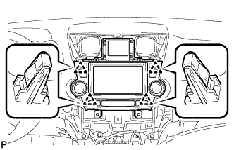
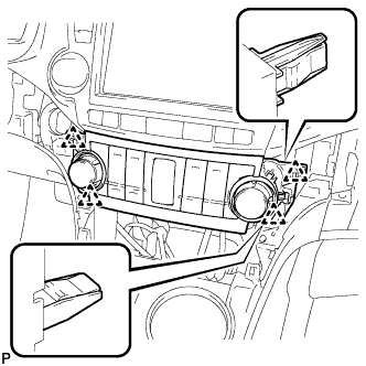
INSTALL AIR CONDITIONING CONTROL ASSEMBLY (for Automatic Air Conditioning System)
|
|
Connect the connector.
- Engage the 4 clips and install the air conditioning control assembly.
| 16.
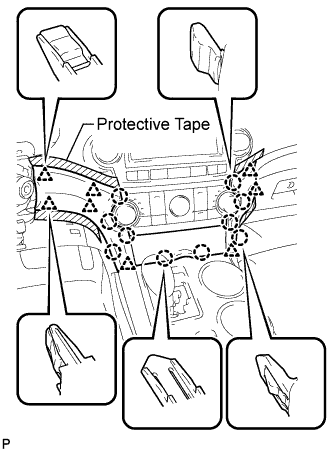
INSTALL CENTER INSTRUMENT CLUSTER FINISH PANEL ASSEMBLY (w/o Smart Entry and Start System)
|
|
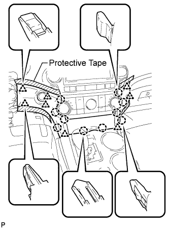
- Apply protective tape to the areas shown in the illustration.
Connect each connector.
Engage the 10 claws and 8 clips, and install the center instrument cluster finish panel assembly.
- NOTICE:
- Do not the damage the instrument panel safety pad assembly and lower instrument panel finish panel sub-assembly.
| 17.
INSTALL CENTER INSTRUMENT CLUSTER FINISH PANEL ASSEMBLY (w/ Smart Entry and Start System)
|
|
- Apply protective tape to the areas shown in the illustration.
Connect each connector.
Engage the 10 claws and 8 clips, and install the center instrument cluster finish panel assembly.
- NOTICE:
- Do not the damage the instrument panel safety pad assembly and lower instrument panel finish panel sub-assembly.
| 18.
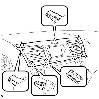
INSTALL CENTER INSTRUMENT PANEL REGISTER ASSEMBLY
|
|
- Engage the 2 claws and 5 clips, and install the center instrument panel register assembly.
| 19.
CONNECT CABLE TO NEGATIVE BATTERY TERMINAL (w/ Navigation System for HDD) |
|
- NOTICE:
- When disconnecting the cable, some systems need to be initialized after the cable is reconnected (Click here).