SYSTEM DIAGRAM
System information · Vehicles built from May 2007
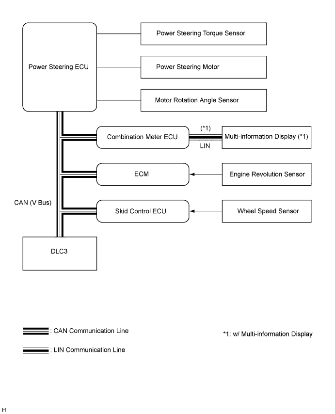

| Sender |
Receiver |
Signal |
Communication Line |
| Skid Control ECU |
Power Steering ECU |
ABS controlling signal (FL wheel) |
CAN |
| ABS controlling signal (FR wheel) |
CAN |
||
| ABS controlling signal (RL wheel) |
CAN |
||
| ABS controlling signal (RR wheel) |
CAN |
||
| VSC operation prohibited signal |
CAN |
||
| Yaw rate deviation signal |
CAN |
||
| TRC controlling signal (FL wheel) |
CAN |
||
| TRC controlling signal (FR wheel) |
CAN |
||
| Estimated brake hydraulic pressure difference (between FR and FL wheels) signal |
CAN |
||
| Power Steering ECU |
ECM |
EPS idle up request signal |
CAN |
| Power Steering ECU |
Combination Meter ECU |
EPS warning light signal (*1) Master warning light signal (*2) |
CAN |
| Combination Meter ECU |
Multi-information Display |
EPS system abnormal signal (*2) |
LIN |
| ECM |
Power Steering ECU |
Engine revolution signal |
CAN |
*2: w/ Multi-information Display