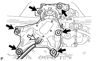
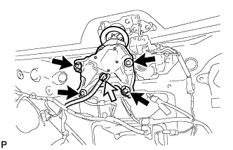
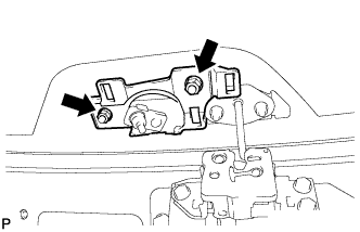
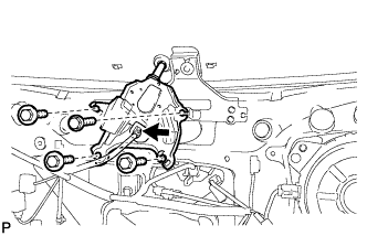
Removal / installation · Vehicles built May 2007 – Jun 2010
Versions by build date: May 2007 – Jun 2010from Jul 2010
1.
PRECAUTION
NOTICE:
For the glass hatch type, if any of the following parts are removed and installed or adjusted, the location of the axis of the rear wiper motor assembly will change, causing the wiping angle to change. Be sure to remove and install the rear wiper motor assembly using the centering jig.
Back door glass
Rear wiper motor assembly
Back door hinge assembly
Rear wiper link pivot
Back window stay assembly
Rear spoiler sub-assembly
Back window lock assembly
-
2.
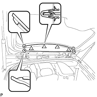
REMOVE BACK WINDOW UPPER TRIM PANEL ASSEMBLY
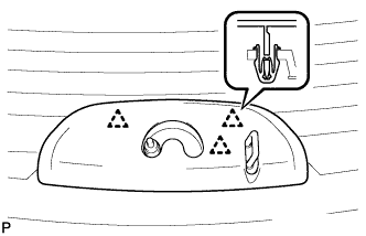
Disengage the 4 clips and 4 claws, and remove the back window upper trim panel assembly.
3.
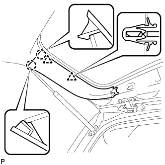
REMOVE BACK DOOR TRIM COVER LH (w/o Power Back Door)
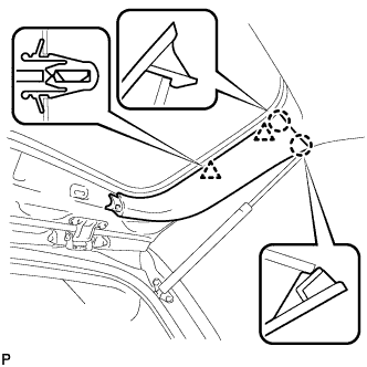
Disengage the 2 clips and 2 claws, and remove the back door trim cover LH.
4.
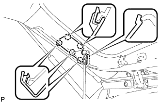
REMOVE BACK DOOR SERVICE HOLE COVER LH (w/ Power Back Door)
Disengage the 6 claws, and remove the back door service hole cover LH.
5.
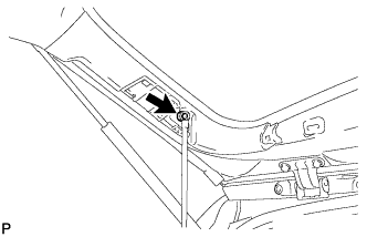
DISCONNECT POWER BACK DOOR ROD (w/ Power Back Door)
Disconnect the power back door rod and remove the back door stay plate.
6.
REMOVE BACK DOOR TRIM COVER LH (w/ Power Back Door)
Disengage the 2 clips and 2 claws, and remove the back door trim cover LH.
7.
REMOVE BACK DOOR TRIM COVER RH
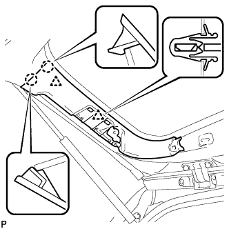
Disengage the 2 clips and 2 claws, and remove the back door trim cover RH.
8.
REMOVE BACK DOOR LOCK COVER (for Glass Hatch Type)
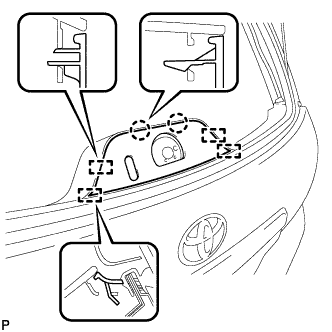
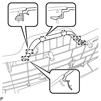
Disengage the 2 claws and 4 guides, and remove the back door lock cover.
9.
REMOVE ASSIST STRAP HOLE COVER
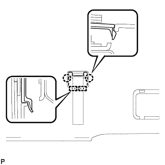
Disengage the 2 claws and 2 guides, and remove the assist strap hole cover.
10.
REMOVE ASSIST STRAP ASSEMBLY
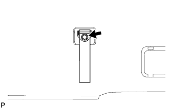
Remove the bolt and assist strap assembly.
11.
REMOVE BACK DOOR TRIM PANEL ASSEMBLY
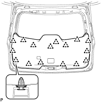
Disengage the 16 clips and remove the back door trim panel assembly.
12.
REMOVE BACK DOOR LOCK COVER (for Fixed Glass Type)
Disengage the 2 claws and 4 guides, and remove the back door lock cover.
13.
REMOVE BACK PANEL TRIM BRACKET SUB-ASSEMBLY
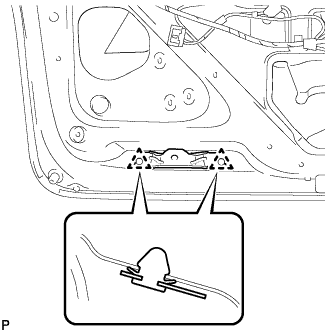
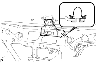
Disengage the 2 clips and remove the back panel trim bracket sub-assembly.
14.
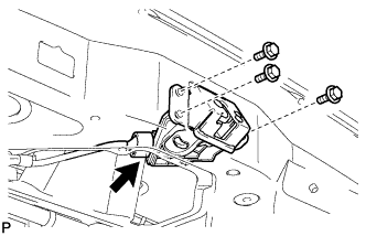
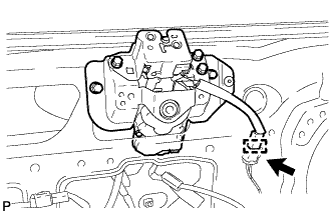
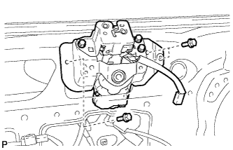
REMOVE BACK DOOR LOCK ASSEMBLY (w/o Power Back Door)
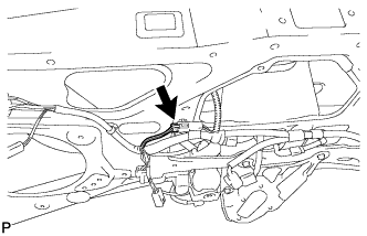
Disconnect the connector.
Remove the 3 bolts and back door lock assembly.
15.
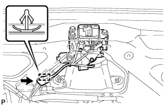
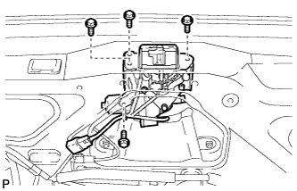
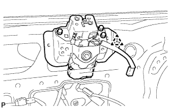
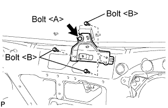
REMOVE BACK DOOR LOCK ASSEMBLY (w/ Power Back Door)
Disconnect the connector.
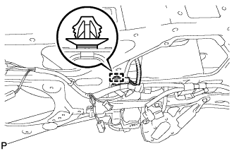
Disengage the clamp.
Remove the 4 bolts and back door lock assembly.
16.
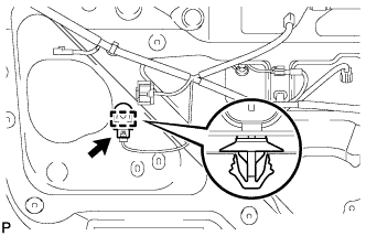
REMOVE POWER BACK DOOR WARNING BUZZER (w/ Power Back Door)
Disconnect the connector.
Disengage the clamp and remove the power back door warning buzzer.
17.
REMOVE POWER BACK DOOR MAIN SWITCH (w/ Power Back Door)
Disconnect the connector.
Disengage the clamp.
Disengage the 4 claws and remove the back door control switch.
18.
REMOVE POWER BACK DOOR SENSOR ASSEMBLY LH (w/ Power Back Door)
Disconnect the connector.
Remove the 4 bolts.
Disengage the 2 clips and remove the power back door sensor assembly.
19.
REMOVE POWER BACK DOOR SENSOR ASSEMBLY RH (w/ Power Back Door)
HINT:
Use the same procedure for the RH side and the LH side.
20.
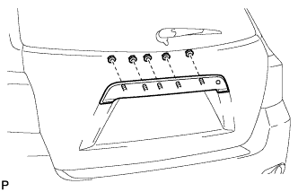
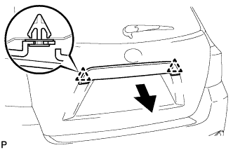
REMOVE BACK DOOR OUTSIDE GARNISH ASSEMBLY
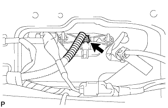
Disconnect each connector.
Remove the 5 nuts.
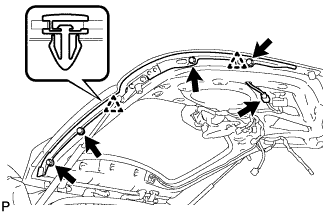
Disengage the 2 clips and remove the back door outside garnish assembly.
Remove the 2 clips and 5 gaskets.
21.
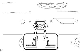
REMOVE TELEVISION CAMERA ASSEMBLY (w/ Rear View Monitor System)
Disconnect the television camera connector.
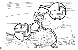
Disengage the 2 claws and remove the television camera assembly.