REMOVAL
Removal / installation · Vehicles built May 2007 – Jul 2008
Versions by build date: May 2007 – Jul 2008 Aug 2008 – Jun 2010 from Jul 2010
| 1.
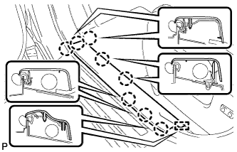
REMOVE FRONT DOOR SCUFF PLATE LH
|
 |
- Disengage the 8 claws and guide, and remove the front door scuff plate LH.
| 2.
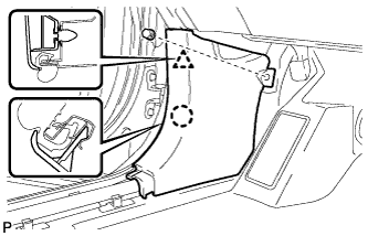
REMOVE COWL SIDE TRIM SUB-ASSEMBLY LH
|
|
- Remove the clip.
Disengage the clip and claw, and remove the cowl side trim sub-assembly LH.
| 3.
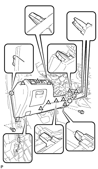
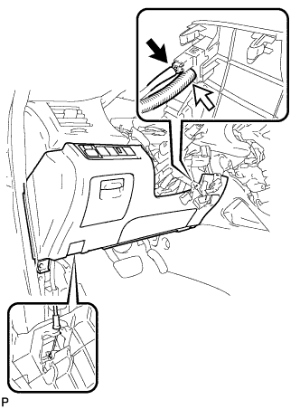
REMOVE LOWER INSTRUMENT PANEL FINISH PANEL SUB-ASSEMBLY (for Manual Air Conditioning System)
|
|
- Remove the 2 bolts <B>.
Disengage the 3 claws and 10 clips.
Disconnect each connector.
Disconnect the hood lock control cable assembly and remove the lower instrument panel finish panel sub-assembly.
| 4.
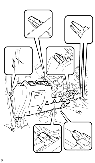
REMOVE LOWER INSTRUMENT PANEL FINISH PANEL SUB-ASSEMBLY (for Automatic Air Conditioning System)
|
|
- Remove the 2 bolts <B>.
Disengage the 3 claws and 10 clips.
- Disconnect each connector and the aspirator duct.
Disconnect the hood lock control cable assembly and remove the lower instrument panel finish panel sub-assembly.
| 5.
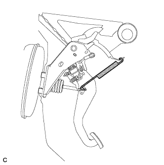
REMOVE BRAKE PEDAL RETURN SPRING |
|
- Remove the brake pedal return spring from the push rod pin and instrument panel reinforcement.
| 6.
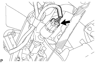
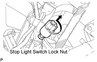
REMOVE STOP LIGHT SWITCH ASSEMBLY
|
|
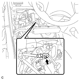
- Disconnect the connector.
- Loosen the stop light switch lock nut.
Remove the stop light switch assembly as shown in the illustration.
| 7.
SEPARATE BRAKE MASTER CYLINDER PUSH ROD CLEVIS |
|
Remove the clip and push rod pin, and separate the brake master cylinder push rod clevis from the brake pedal sub-assembly.
| 8.
REMOVE BRAKE PEDAL SUPPORT SUB-ASSEMBLY (for LHD) |
|
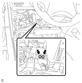
- Disconnect the brake pedal load sensing switch connector and disengage the clamp.
- Remove the 2 bolts and separate the brake pedal support sub-assembly from the instrument panel reinforcement.
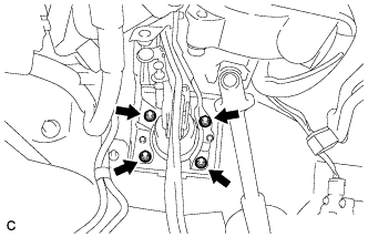
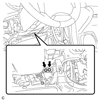
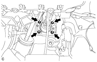
- Remove the 4 nuts and brake pedal support sub-assembly from the body.
| 9.
REMOVE BRAKE PEDAL SUPPORT SUB-ASSEMBLY (for RHD) |
|
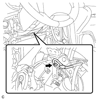
- Disconnect the brake pedal load sensing switch connector and disengage the clamp.
- Remove the 2 bolts and separate the brake pedal support sub-assembly from the instrument panel reinforcement.
- Remove the 4 nuts and brake pedal support sub-assembly from the body.