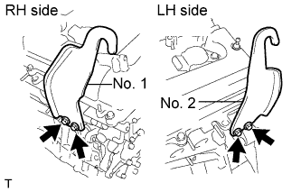
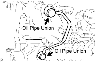
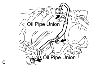
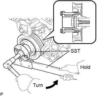
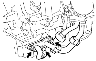
Remove the bolt and 2 nuts, and disconnect the oil cooler pipe from the oil pan sub-assembly.
Remove the gasket from the oil pan sub-assembly.
7.
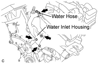
REMOVE WATER INLET HOUSING
Disconnect the water hose.
Remove the 2 bolts, nut and water inlet housing.
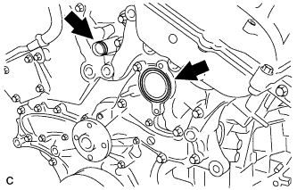
Remove the water inlet housing gasket and water outlet pipe O-ring.
8.
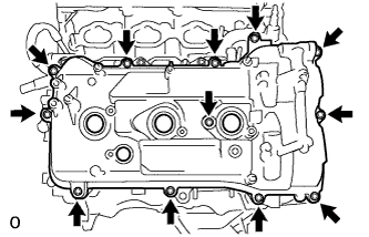
REMOVE CYLINDER HEAD COVER SUB-ASSEMBLY (for Bank 1)
Remove the 12 bolts, seal washer, cylinder head cover sub-assembly and cylinder head cover gasket.
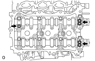
Remove the 3 gaskets.
9.
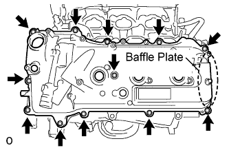
REMOVE CYLINDER HEAD COVER SUB-ASSEMBLY (for Bank 2)
Remove the 12 bolts, seal washer, cylinder head cover sub-assembly and cylinder head cover gasket.
NOTICE:
The baffle plate is located on the back of the portion shown in the illustration. Do not damage the baffle plate when removing the cylinder head cover sub-assembly.
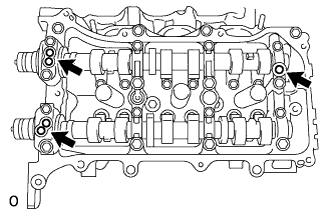
Remove the 3 gaskets.
10.
REMOVE NO. 2 OIL PAN SUB-ASSEMBLY
Remove the 16 bolts and 2 nuts.
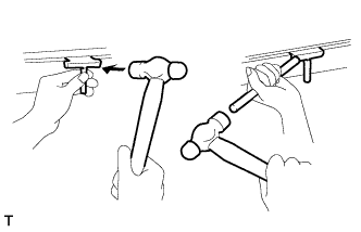
Insert the blade of oil pan seal cutter between the oil pans. Cut through the applied sealer and remove the No. 2 oil pan sub-assembly.
NOTICE:
Be careful not to damage the contact surfaces of the oil pans.
Using a "TORX" socket wrench E6, remove the 2 stud bolts.
11.
REMOVE OIL STRAINER SUB-ASSEMBLY
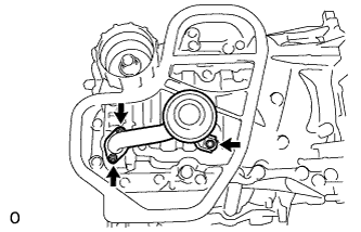
Remove the bolt, 2 nuts, oil strainer sub-assembly and gasket.
Using a "TORX" socket wrench E6, remove the 2 stud bolts.
12.
REMOVE OIL PAN SUB-ASSEMBLY
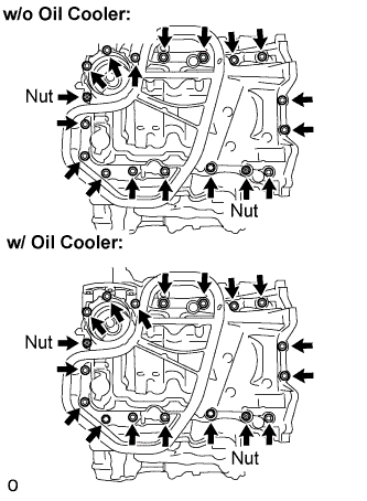
Remove the 16 bolts and 2 nuts.
HINT:
Be sure to clean the bolts and stud bolts and check the threads for cracks or other damage.
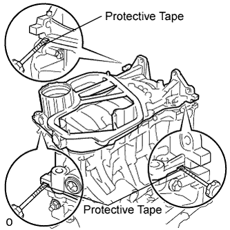
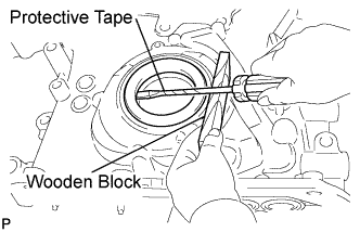
Remove the oil pan sub-assembly by prying between the oil pan sub-assembly and cylinder block sub-assembly with a screwdriver.
NOTICE:
Be careful not to damage the contact surfaces of the cylinder block and oil pan.
HINT:
Tape the screwdriver tip before use.
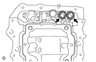
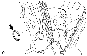
Remove the 2 O-rings.
Using a "TORX" socket wrench E8, remove the 2 stud bolts.
13.
REMOVE TIMING CHAIN COVER SUB-ASSEMBLY
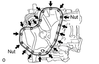
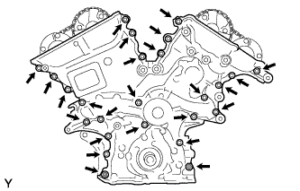
Remove the 23 bolts and 2 nuts as shown in the illustration.
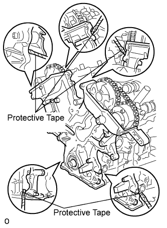
Remove the timing chain cover by prying between the timing chain cover and cylinder head or cylinder block with a screwdriver.
NOTICE:
Be careful not to damage the contact surfaces of the cylinder head, cylinder block and chain cover.