REMOVAL
Removal / installation · Vehicles built from Jul 2010
Versions by build date: May 2007 – Jul 2008 Aug 2008 – Jun 2010 from Jul 2010
| 1.
REMOVE ENGINE ASSEMBLY WITH TRANSAXLE |
 |
- HINT:
- Remove engine assembly with transaxle (Click here).
| 2.
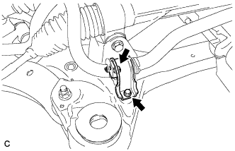
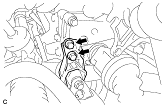
REMOVE NO. 1 FRONT STABILIZER BRACKET LH
|
|
- Remove the 2 bolts and the No. 1 front stabilizer bracket LH from the front frame assembly.
| 3.
REMOVE NO. 1 FRONT STABILIZER BRACKET RH |
|
- HINT:
- Perform the same procedure as the LH side.
| 4.
REMOVE FRONT STABILIZER BAR WITH FRONT STABILIZER LINK ASSEMBLY |
|
| 5.
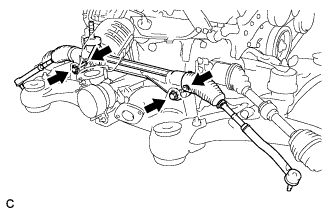
REMOVE POWER STEERING LINK ASSEMBLY
|
|
- Remove the 2 bolts, 2 nuts, and power steering link assembly.
- NOTICE:
- Because the nut has its own stopper, do not turn the nut. Loosen the bolt with the nut fixed.
| 6.
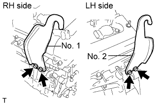
INSTALL ENGINE HANGERS
|
|
- Install the 2 engine hangers with the 4 bolts as shown in the illustration.
- Part No.:
- No. 1 engine hanger 12281-31120
No. 2 engine hanger 12282-31100
Bolts 91671-10825
-
Torque:
- 33 N*m{
337 kgf*cm
, 24 ft.*lbf
}
Attach the engine sling device and hang the engine with the chain block.
| 7.
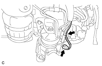
REMOVE FRONT FRAME ASSEMBLY
|
|
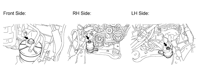
- Disconnect the active mount VSV connector and harness clamp.
Loosen the bolt and 2 nuts.

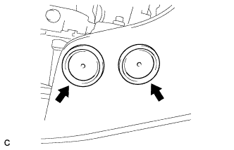
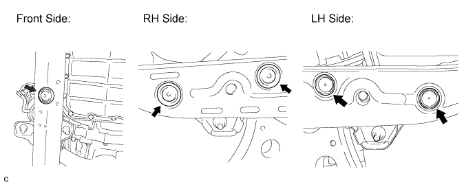
Remove the 5 hole plugs.
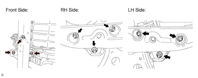
Remove the 9 nuts.
- Remove the 2 bolts and separate the engine with transaxle from the front frame assembly.
| 8.
REMOVE TRANSVERSE ENGINE MOUNTING INSULATOR
|
|
- Remove the 2 hole plugs.
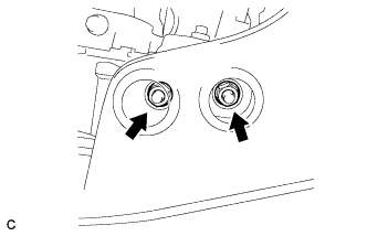
- Remove the 2 nuts and transverse engine mounting insulator.
| 9.
REMOVE FRONT LOWER SUSPENSION ARM LH
|
|
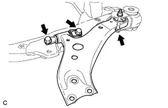
- Remove the 3 bolts, nut, and the front lower suspension arm from the front frame assembly.
Remove the front lower arm bushing stopper from the front lower suspension arm.
| 10.
REMOVE FRONT LOWER SUSPENSION ARM RH |
|
- HINT:
- Perform the same procedure as the LH side.
| 11.
REMOVE FRONT SUSPENSION MEMBER DYNAMIC DAMPER |
|
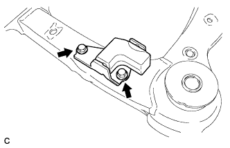
- Remove the 2 bolts and front suspension member dynamic damper.
| 12.
REMOVE FRONT SUSPENSION MEMBER BODY MOUNTING FRONT STOPPER |
|
| 13.
REMOVE FRONT SUSPENSION MEMBER BODY MOUNTING REAR STOPPER |
|
| 14.
REMOVE FRONT SUSPENSION MEMBER BODY MOUNTING FRONT CUSHION |
|
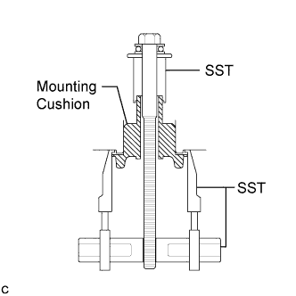
- Install SST as shown in the illustration.
- SST
- 09830-10010
(09830-01010, 09830-01040, 09830-01050)
09950-40011
(09951-04020, 09952-04010, 09955-04011)
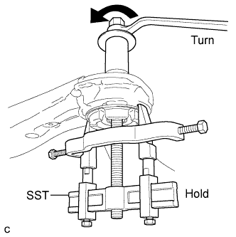
- Using SST, remove the front suspension member body mounting front cushion.
- NOTICE:
- Make sure that the claws of SST are securely hung onto the mounting cushion.
- Tighten SST slowly and evenly.
- Be careful as the mounting cushion may fly out.
- The mounting cushion cannot be reused.
| 15.
REMOVE FRONT SUSPENSION MEMBER BODY MOUNTING REAR CUSHION LH |
|
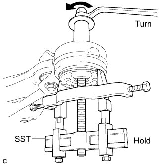
- Using SST, remove the front suspension member body mounting rear cushion LH.
- SST
- 09830-10010
(09830-01010, 09830-01040, 09830-01050)
09950-40011
(09951-04020, 09952-04010, 09954-04010, 09955-04011)
- NOTICE:
- Make sure that the claws of SST are securely hung onto the mounting cushion.
- Tighten SST slowly and evenly.
- Be careful as the mounting cushion may fly out.
- The mounting cushion cannot be reused.
| 16.
REMOVE FRONT SUSPENSION MEMBER BODY MOUNTING REAR CUSHION RH |
|
- HINT:
- Perform the same procedure as the LH side.
- SST
- 09830-10010
(09830-01010, 09830-01040, 09830-01050)
09950-40011
(09951-04020, 09952-04010, 09954-04010, 09955-04011)