INSTALLATION
Removal / installation · Vehicles built May 2007 – Jul 2008
Versions by build date: May 2007 – Jul 2008 Aug 2008 – Jun 2010 from Jul 2010
| 1.
INSTALL FRONT FENDER LINER LH |
 |
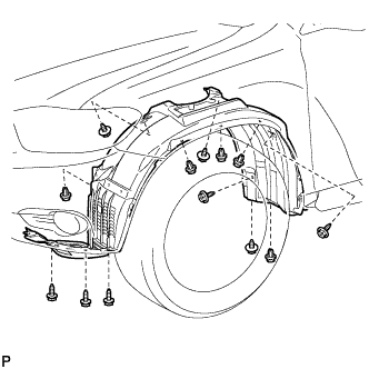
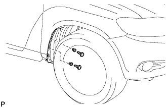
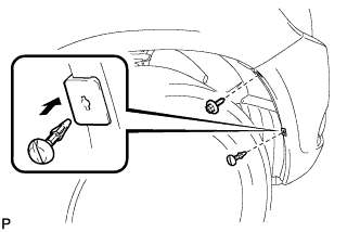
- Install the front fender liner LH with the 5 clips and 8 screws.
- Install 2 new grommets.
Using a 4 mm hexagon wrench, install the 2 screws.
- Install the screw and pin hold clip.
-
Torque:
- 3.0 N*m{
31 kgf*cm
, 27 in.*lbf
}
| 2.
INSTALL FRONT FENDER LINER RH |
|
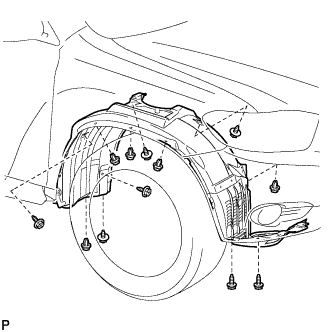
- Install the front fender liner RH with the 5 clips and 7 screws.
- Install 2 new grommets.
Using a 4 mm hexagon wrench, install the 2 screws.
- Install the screw and pin hold clip.
-
Torque:
- 3.0 N*m{
31 kgf*cm
, 27 in.*lbf
}
| 3.
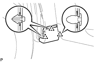
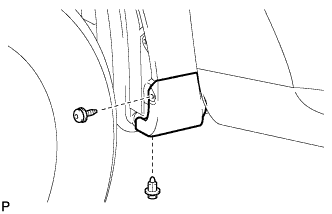
INSTALL FRONT WHEEL OPENING EXTENSION PAD (for LH Side) |
|
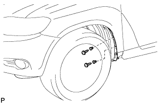
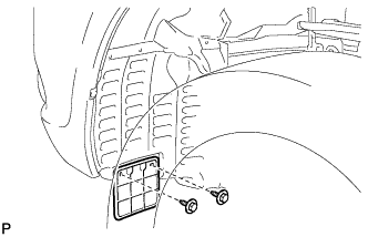
- Install the front wheel opening extension pad with the 2 screws.
| 4.
INSTALL FRONT WHEEL OPENING EXTENSION PAD (for RH Side) |
|
- HINT:
- Use the same procedure for the RH side and LH side.
| 5.
INSTALL FRONT FENDER MOULDING SUB-ASSEMBLY LH
|
|
Clean the vehicle body surface.
Using a heat light, heat the vehicle body surface.
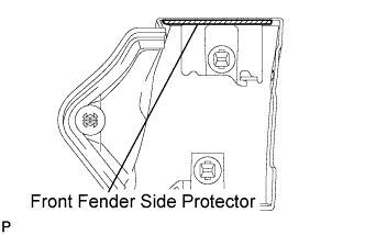
Remove the front fender side protector from the vehicle body.
Wipe off any tape adhesive residue with cleaner.
- Clean the front fender moulding sub-assembly. (If reusing the front fender moulding sub-assembly)
Using a heat light, heat the front fender moulding sub-assembly.
Remove the front fender side protector from the front fender moulding sub-assembly.
Wipe off any tape adhesive residue with cleaner.
Install a new front fender side protector to the the front fender moulding sub-assembly.
Install 2 new No. 4 clips on the front fender moulding sub-assembly.
Install a new pad on the front fender moulding sub-assembly.
- Install the front fender moulding sub-assembly.
Using a heat light, heat the vehicle body and the front fender moulding sub-assembly.
Remove the release paper from the front fender moulding sub-assembly.
- HINT:
- After removing the release paper, keep the exposed adhesive free from foreign matter.
Engage the 3 clips and install the front fender moulding sub-assembly.
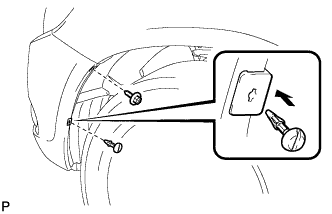
- Using a 4 mm hexagon wrench, install the screw.
Install the clip.
| 6.
INSTALL FRONT FENDER MOULDING SUB-ASSEMBLY RH |
|
- HINT:
- Use the same procedures for the RH side and LH side.
| 7.
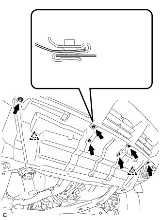
INSTALL NO. 1 ENGINE UNDER COVER
|
|
- Install the No. 1 engine under cover with the 6 bolts and 2 clips.
| 8.
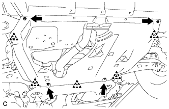
INSTALL ENGINE UNDER COVER ASSEMBLY
|
|
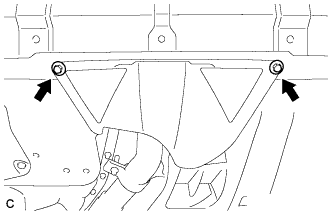
- Install the engine under cover assembly with the 2 bolts, 2 screws and 5 clips.
- Install the engine under cover assembly RR with the 2 bolts.