INSTALLATION
Removal / installation · Vehicles built Aug 2008 – Jun 2010
Versions by build date: May 2007 – Jul 2008 Aug 2008 – Jun 2010 from Jul 2010
| 1.
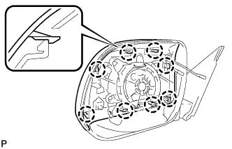
INSTALL OUTER MIRROR COVER
|
 |
- Engage the 8 claws to install the outer mirror cover to the outer rear view mirror assembly with cover.
- NOTICE:
- If there is a gap between the cover and the mirror body, it may cause noise during driving.
| 2.
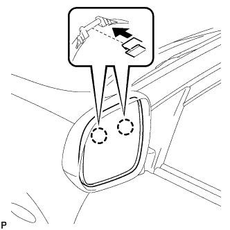
INSTALL OUTER MIRROR GLASS (w/o Heater)
|
|
- Engage the 2 claws on the upper part of the outer mirror glass to the outer mirror.
- Engage the 2 claws on the lower part of the outer mirror glass to the outer mirror as shown in the illustration.
| 3.
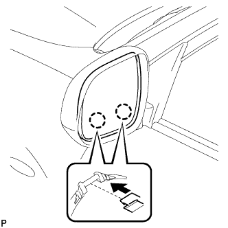
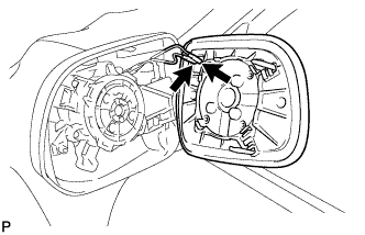
INSTALL OUTER MIRROR GLASS (w/ Heater)
|
|
- Connect the connectors.
- Engage the 2 claws on the upper part of the outer mirror glass to the outer mirror.
- Engage the 2 claws on the lower part of the outer mirror glass to the outer mirror as shown in the illustration.
| 4.
INSTALL OUTER REAR VIEW MIRROR ASSEMBLY WITH COVER
|
|
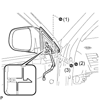
- Engage the claw, and temporarily install the outer rear view mirror assembly with cover.
Tighten the 3 nuts in the order shown in the illustration to install the outer rear view mirror assembly with cover.
-
Torque:
- 8.0 N*m{
82 kgf*cm
, 71 in.*lbf
}
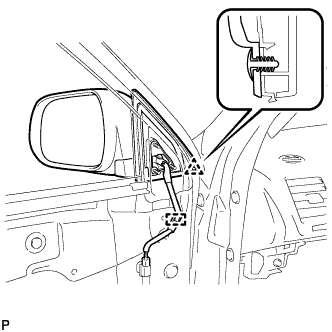
- Engage the clamp and connect the connector.
Install the clip.
| 5.
INSTALL FRONT DOOR TRIM BOARD SUB-ASSEMBLY
|
|
Connect the connector.
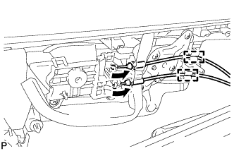
- Connect the front door lock remote control cable and front door inside locking cable to the front door inside handle sub-assembly.
Engage the 2 clamps.
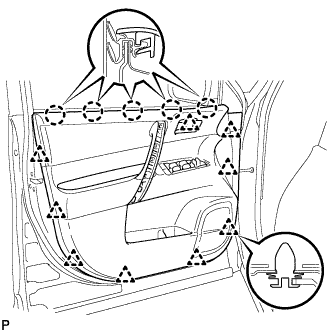
- Engage the front door trim board with the 5 claws on the front door inner glass weatherstrip.
Engage the 9 clips.
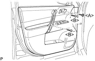
- Install the 2 screws <B>.
Install the screw <A> and front door trim board to the front door panel.
-
Torque:
- 3.5 N*m{
36 kgf*cm
, 31 in.*lbf
}
| 6.
INSTALL COURTESY LIGHT ASSEMBLY
|
|
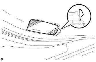
Connect the connector.
- Engage the claw and install the courtesy light assembly.
| 7.
INSTALL ASSIST GRIP COVER
|
|
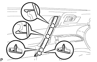
- Engage the 4 claws and install the assist grip cover.
| 8.
INSTALL FRONT ARMREST UPPER BASE PANEL
|
|
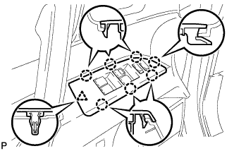
Connect the connector.
- Engage the 7 claws and clip and install the front armrest upper base panel.
| 9.
INSTALL FRONT DOOR INSIDE HANDLE BEZEL PLUG
|
|
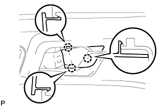
- Engage the 3 claws and install the front door inside handle bezel plug.
| 10.
INSTALL FRONT DOOR LOWER FRAME BRACKET GARNISH
|
|
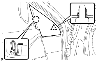
- Engage the clip and claw, and install the front door lower frame bracket garnish.