Home › BODY ELECTRICAL › LIGHTING › STOP LIGHT SWITCHINSTALLATION
Removal / installation · Vehicles built from Jul 2010
Versions by build date: May 2007 – Jul 2008 Aug 2008 – Jun 2010 from Jul 2010
1.
INSTALL STOP LIGHT SWITCH ASSEMBLY
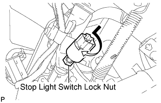
Temporarily install the stop light switch assembly with the stop light switch lock nut.
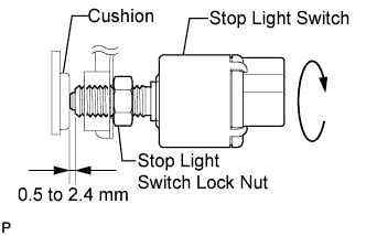
Turn the stop light switch assembly so that the clearance between the nut end and stop light switch cushion is between 0.5 to 2.4 mm (0.020 to 0.095 in.). Tighten the stop light switch lock nut.
Torque:
17 N*m{
173 kgf*cm
, 12 ft.*lbf
}
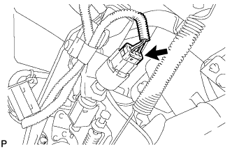
Connect the connector.
2.
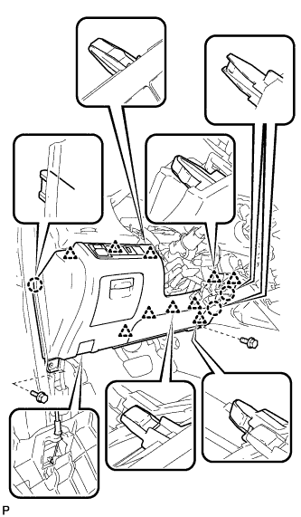
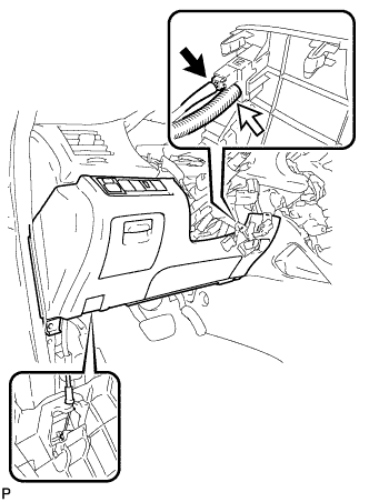
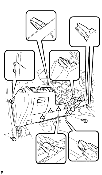
INSTALL LOWER INSTRUMENT PANEL FINISH PANEL SUB-ASSEMBLY (for Manual Air Conditioning System)
Connect the hood lock control cable assembly. Connect each connector.
Engage the 3 claws and 10 clips.
Install the lower instrument panel finish panel sub-assembly with the 2 bolts <B>.
3.
INSTALL LOWER INSTRUMENT PANEL FINISH PANEL SUB-ASSEMBLY (for Automatic Air Conditioning System)
Connect the hood lock control cable assembly. Connect each connector and the aspirator duct.
Engage the 3 claws and 10 clips. Install the lower instrument panel finish panel sub-assembly with the 2 bolts <B>.
4.
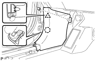
INSTALL COWL SIDE TRIM SUB-ASSEMBLY LH
Engage the claw and clip, install the cowl side trim sub-assembly LH. Install the clip.
5.
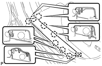
INSTALL FRONT DOOR SCUFF PLATE LH
Engage the guide and 8 claws, and install the front door scuff plate LH.