Home › BODY › ENGINE HOOD / DOOR › POWER BACK DOOR DRIVE UNITINSTALLATION
Removal / installation · Vehicles built from Jul 2010
Versions by build date: May 2007 – Jul 2008 Aug 2008 – Jun 2010 from Jul 2010
1.
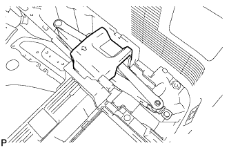
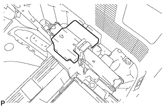
INSTALL BACK DOOR MOTOR UNIT
When reusing the back door motor unit:
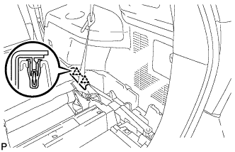
Engage the clip.
Install the back door motor unit with the 4 bolts.
Torque:
14 N*m{
143 kgf*cm
, 10 ft.*lbf
}
Connect the connector.
Install the back door stay plate with the back door stay bolt.
Torque:
18 N*m{
184 kgf*cm
, 13 ft.*lbf
}
When installing a new back door motor unit:
Engage the clip.
Install a new back door motor unit with the 4 bolts.
Torque:
14 N*m{
143 kgf*cm
, 10 ft.*lbf
}
Connect the connector.
Install the back door stay plate with a new back door stay bolt.
Torque:
18 N*m{
184 kgf*cm
, 13 ft.*lbf
}
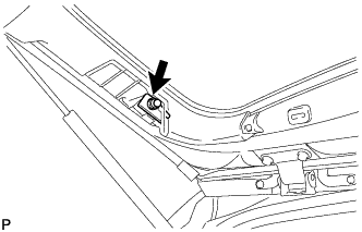
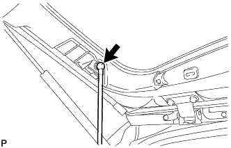
Attach the ball joint to install a new power back door rod.
When installing a new back door upper rod:
Engage the clip.
Install the back door motor unit with the 4 bolts.
Torque:
14 N*m{
143 kgf*cm
, 10 ft.*lbf
}
Connect the connector.
Install a new back door stay plate with a new back door stay bolt.
Torque:
18 N*m{
184 kgf*cm
, 13 ft.*lbf
}
Attach the ball joint to install a new power back door rod.
2.
INSTALL BACK DOOR SERVICE HOLE COVER LH
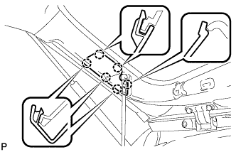
Engage the 6 claws and install the back door service hole cover LH.
3.
INSTALL BACK WINDOW UPPER TRIM PANEL ASSEMBLY
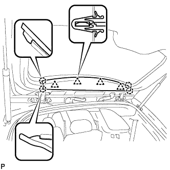
Engage the 4 clips and 4 claws, and install the back window upper trim panel assembly.
4.
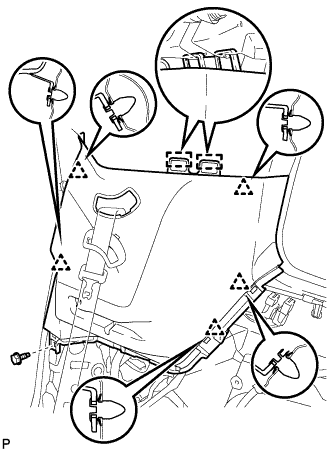
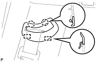
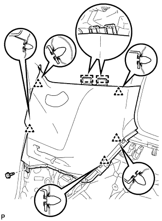
INSTALL ROOF SIDE INNER GARNISH ASSEMBLY LH
w/ Rear No. 2 Seat:
Engage the 2 guides and 5 clips. Install the roof side inner garnish assembly LH with the bolt.
Engage the 2 guides and 2 claws, and install the No. 2 seat outer belt guide.
w/o Rear No. 2 Seat:
Engage the 2 guides and 5 clips. Install the roof side inner garnish assembly LH with the bolt.
5.
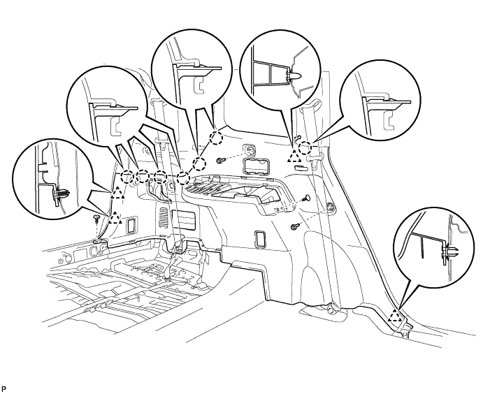
INSTALL DECK TRIM SIDE PANEL ASSEMBLY LH
Engage the 4 clips and 7 claws.
Install the 2 clips.
Install the deck trim side panel assembly LH with the 2 bolts.
6.
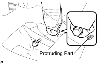
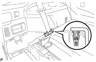
CONNECT REAR NO. 1 SEAT OUTER BELT ASSEMBLY LH
Connect the floor anchor end of the rear No. 1 seat outer belt assembly and install the bolt.
Torque:
42 N*m{
428 kgf*cm
, 31 ft.*lbf
}
NOTICE:
Do not allow the anchor part of the rear No. 1 seat outer belt assembly to overlap the protruding part of the floor panel.
7.
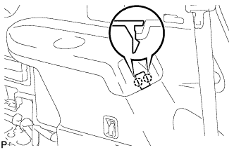
INSTALL FRONT DECK SIDE TRIM COVER LH
Engage the 4 claws and install the 2 front deck side trim covers LH.
8.
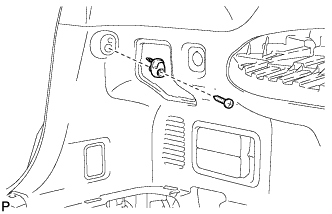
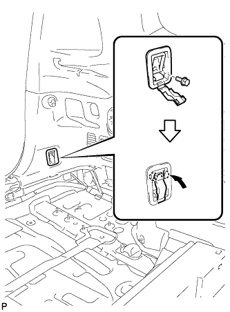
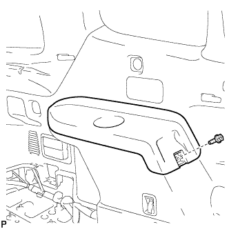
INSTALL NO. 2 DECK SIDE TRIM HOOK
Install the No. 2 deck side trim hook with the screw.
9.
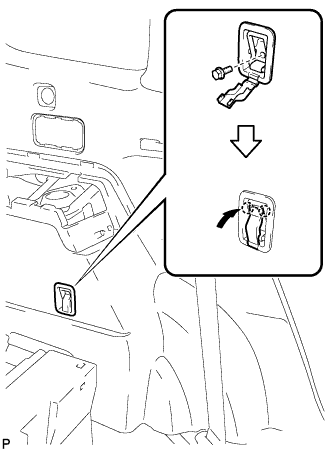
INSTALL ROPE HOOK ASSEMBLY
for Front Side:
Install the rope hook assembly with the bolt.
Torque:
6.5 N*m{
66 kgf*cm
, 58 in.*lbf
}
Engage the 2 claws.
for Rear Side:
Install the rope hook assembly with the bolt.
Torque:
6.5 N*m{
66 kgf*cm
, 58 in.*lbf
}
Engage the 2 claws.
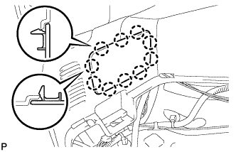
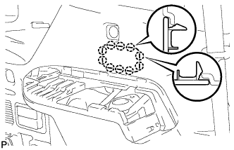
10.
INSTALL REAR DECK TRIM COVER (w/o Remote Folding Function)
Engage the 10 claws to install the rear deck trim cover.
11.
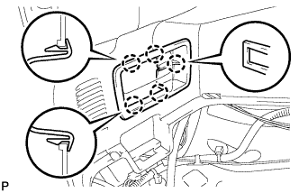
INSTALL RECLINING REMOTE CONTROL LEVER BEZEL LH (w/ Remote Folding Function)
Engage the 5 claws to install the reclining remote control lever bezel LH.
12.
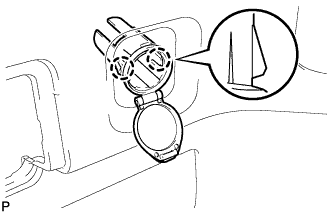
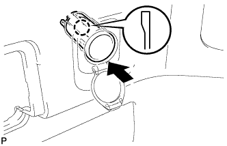
INSTALL REAR POWER OUTLET SOCKET COVER
Engage the 2 claws and install the rear power outlet socket cover.
13.
INSTALL REAR POWER POINT SOCKET ASSEMBLY
Engage the claw and install the rear power point socket assembly. Connect the connector.
14.
INSTALL REAR COMBINATION LIGHT SERVICE COVER LH
Engage the 2 guides and 6 claws, and install the rear combination light service cover LH.
15.
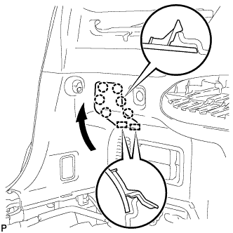
INSTALL SIDE TRIM COVER LH
Engage the 10 claws and install the side trim cover LH.
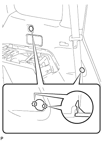
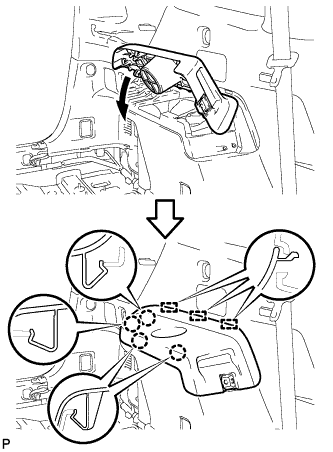
16.
INSTALL DECK SIDE TRIM LH
Engage the 3 guides and 4 claws as shown in the illustration.
Install the deck side trim LH with the bolt.
17.
INSTALL DECK SIDE TRIM COVER NO.2
Engage the 2 claws and install the deck side trim cover LH.
18.
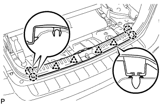
INSTALL REAR FLOOR FINISH PLATE
Engage the 4 clips and 4 claws, and install the rear floor finish plate.
19.
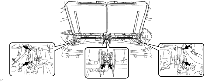
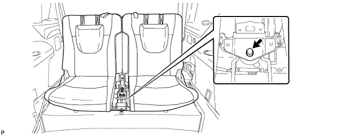
INSTALL REAR NO. 2 SEAT ASSEMBLY (w/ Rear No. 2 Seat)
Install the 6 bolts on the rear of the seat.
Torque:
37 N*m{
377 kgf*cm
, 27 ft.*lbf
}
Install the rear No. 2 seat assembly with the bolt.
Torque:
37 N*m{
377 kgf*cm
, 27 ft.*lbf
}
20.
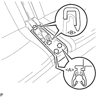
INSTALL CENTER SEAT CUSHION COVER SUB-ASSEMBLY
Engage the 2 claws <B>. Engage the 2 claws <A> to install the center seat cushion cover sub-assembly.
21.
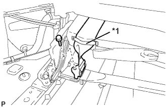
CONNECT REAR NO. 2 SEAT OUTER BELT ASSEMBLY LH (w/ Rear No. 2 Seat)
Route the rear No. 2 seat outer belt assembly LH through the rubber band as shown in the illustration.
Text in Illustration
*1
Rubber Band
Install the rear No. 2 seat outer belt assembly LH with the bolt.
Torque:
42 N*m{
428 kgf*cm
, 31 ft.*lbf
}
NOTICE:
After installing the belt, check that it is not twisted.
22.
CONNECT REAR NO. 2 SEAT OUTER BELT ASSEMBLY RH (w/ Rear No. 2 Seat)
HINT:
Use the same procedure as for the LH side.
23.
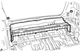
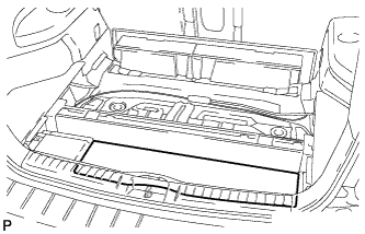
INSTALL REAR DECK FLOOR BOX (w/o Rear No. 2 Seat)
Install the rear deck floor box with the 2 nuts.
24.
INSTALL DECK FLOOR BOARD ASSEMBLY (w/o Rear No. 2 Seat)
Install the 2 nuts and deck floor board assembly. Engage the 3 claws.
25.
INSTALL REAR MAT
Install the rear mat.
26.
INSTALL DECK FLOOR BOARD ASSEMBLY (w/ Rear No. 2 Seat)
Install the rear deck floor board assembly with the 4 nuts and 4 bolts.
27.
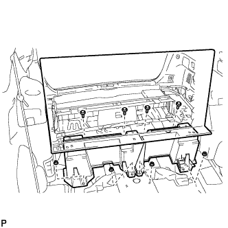
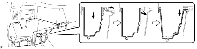
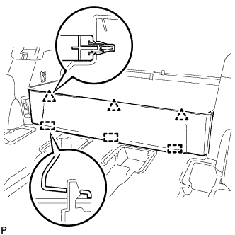
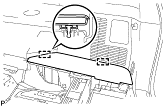
INSTALL DECK SIDE TRIM BOX LH
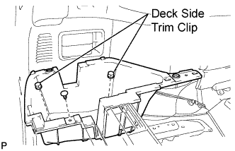
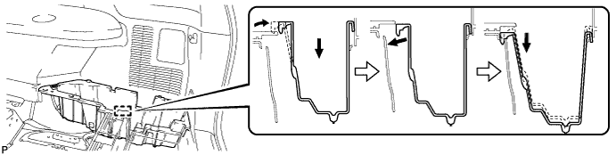
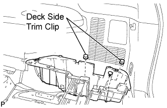
Install the deck side trim box LH as shown in the illustration.
Install the 2 deck side trim clips and clip.
28.
INSTALL REAR SEAT SIDE COVER LH (w/ Rear No. 2 Seat)
Engage the 2 clips and install the rear seat side cover LH.
29.
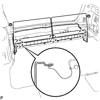
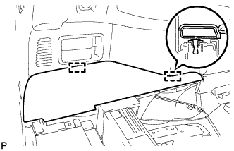
INSTALL DECK SIDE TRIM BOX RH
Install the deck side trim box RH as shown in the illustration.
Install the 2 deck side trim clips and clip.
30.
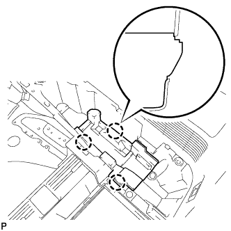
INSTALL JACK CARRIER ASSEMBLY (for LHD)
Engage the 3 claws, and install the jack carrier assembly.
31.
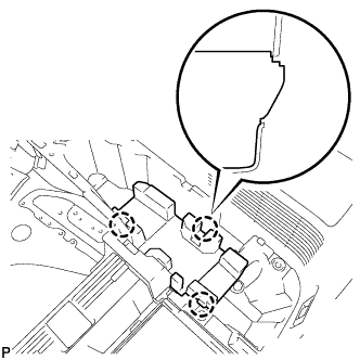
INSTALL JACK CARRIER ASSEMBLY (for RHD)
Engage the 3 claws, and install the jack carrier assembly.
32.
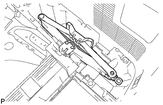
INSTALL JACK ASSEMBLY (for LHD)
Install the jack assembly.
33.
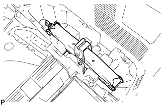
INSTALL JACK ASSEMBLY (for RHD)
Install the jack assembly.
34.
INSTALL JACK CARRIER CUSHION (for LHD)
Install the jack carrier cushion.
35.
INSTALL JACK CARRIER CUSHION (for RHD)
Install the jack carrier cushion.
36.
INSTALL JACK CARRIER SUPPORT
37.
INSTALL REAR SEAT SIDE COVER RH (w/ Rear No. 2 Seat)
Engage the 2 clips and install the rear seat side cover RH.
38.
INSTALL REAR NO. 1 FLOOR BOARD (w/o Rear No. 2 Seat)
Engage the 3 guides and 3 clips and install the rear No. 1 floor board.
39.
INSTALL TONNEAU COVER ASSEMBLY (w/ Tonneau Cover)
40.
INSTALL NO. 2 DECK BOARD SUB-ASSEMBLY
Engage the 2 guides and install the No. 2 deck board sub-assembly.
41.
INSTALL NO. 3 DECK BOARD SUB-ASSEMBLY
Engage the 2 guides and install the No. 3 deck board sub-assembly.
42.
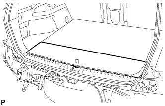
INSTALL DECK BOARD ASSEMBLY
Install the deck board assembly.
43.
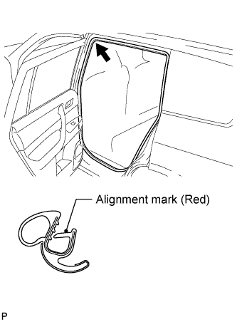
INSTALL REAR DOOR OPENING TRIM WEATHERSTRIP LH
Align the alignment mark (red) on the weatherstrip with the protruding portion on the body indicated by the arrow in the illustration, and install the rear door opening trim weatherstrip LH.
NOTICE:
After installation, check that the corners fit correctly.
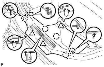
44.
INSTALL REAR DOOR SCUFF PLATE LH
Engage the guide, 3 clips and 5 claws, and install the rear door scuff plate LH.
45.
INITIALIZE POWER BACK DOOR SYSTEM
(Click here )
46.
INSPECT POWER BACK DOOR OPERATION
(Click here )