Power Back Door cannot be Operated Using Any Switch
Circuit diagnosis · Vehicles built Aug 2008 – Jun 2010
Versions by build date: May 2007 – Jul 2008 Aug 2008 – Jun 2010 from Jul 2010
DESCRIPTION
When the power back door cannot be operated using any switch, one of the following may be the cause: 1) initialization of the power back door ECU, or a malfunction in the 2) power back door touch sensor circuit, 3) power back door main switch circuit, 4) back door closer system, 5) meter/gauge system, or 6) main body ECU (instrument panel junction block), or 7) power back door drive unit (power back door ECU).WIRING DIAGRAM
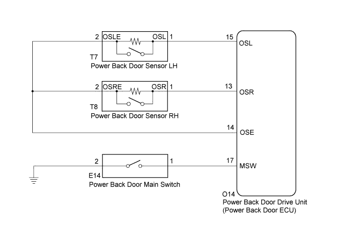

INSPECTION PROCEDURE
| 1. INITIALIZE POWER BACK DOOR ECU |

Check that the power back door drive unit (power back door ECU) can be initialized (Click here).
| NEXT | |
 |
| 2. CHECK POWER BACK DOOR SYSTEM |
Check the power back door system operation.
- OK:
- Power back door system operates normally.
|
|
||||

| OK | ||
 |
||
| ||
| 3. CHECK BACK DOOR CLOSER SYSTEM |
Check the back door closer system operation. (Click here)
|
|
||||

| OK | |
|
| 4. CHECK COMBINATION METER |
Check the A/T shift position indicator operation.
Check that the speedometer indicates 0 mph when the vehicle is stopped and the engine idling.
|
|
||||
| OK | |
|
| 5. CHECK DTC OUTPUT |
Check for the DTCs (Click here).
- Result:
Result
Proceed to
DTC is not output
A
B2250 is output
B
B2251 is output
C
|
|
||||
|
|
||||
| A | |
|
| 6. READ VALUE ON INTELLIGENT TESTER |
Check the Data List to determine if the back door lock function properly.
Main body ECU (Instrument panel junction block) Tester Display
Measurement Item/Range
Normal Condition
Diagnostic Note
Back Dor Open
Back door lock / Permit or prohibit
Permit: Back door is unlocked
Prohibt: Back door is locked
-
- OK:
- The back door functions as specified in the normal condition.
|
|
||||
| OK | |
|
| 7. READ VALUE ON INTELLIGENT TESTER |
Check the Data List to determine if the power back door touch sensor function properly.
Back door (Power back door ECU) Tester Display
Measurement Item/Range
Normal Condition
Diagnostic Note
PBD Touch Sen L
Power back door touch sensor LH signal / ON or OFF
ON: Power back door touch sensor LH pressed
OFF: Power back door touch sensor LH not pressed
-
PBD Touch Sen R
Power back door touch sensor RH signal / ON or OFF
ON: Power back door touch sensor RH pressed
OFF: Power back door touch sensor RH not pressed
-
- OK:
- The power back door touch sensor functions as specified in the normal condition.
|
|
||||
| OK | |
|
| 8. READ VALUE ON INTELLIGENT TESTER |
Check the Data List to determine if the power back door main switch function properly.
Back door (Power back door ECU) Tester Display
Measurement Item/Range
Normal Condition
Diagnostic Note
PBD Main SW
Power back door main switch / ON or OFF
ON: Power back door main switch is not pushed
OFF: Power back door main switch is pushed
-
- OK:
- The power back door main switch functions as specified in the normal condition.
|
|
||||
| OK | ||
|
||
| ||
| 9. INSPECT POWER BACK DOOR MAIN SWITCH |
Remove the power back door main switch (Click here).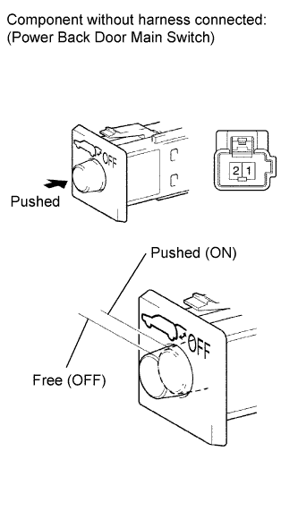
Measure the resistance according to the value(s) in the table below.
- Standard resistance:
Tester Connection
Switch Position
Specified Condition
1 - 2
Free (OFF)
10 kΩ or higher
1 - 2
Pushed (ON)
Below 1 Ω
|
|
||||
| OK | |
|
| 10. CHECK HARNESS AND CONNECTOR (POWER BACK DOOR MAIN SWITCH - POWER BACK DOOR ECU) |
Disconnect the E14 switch connector.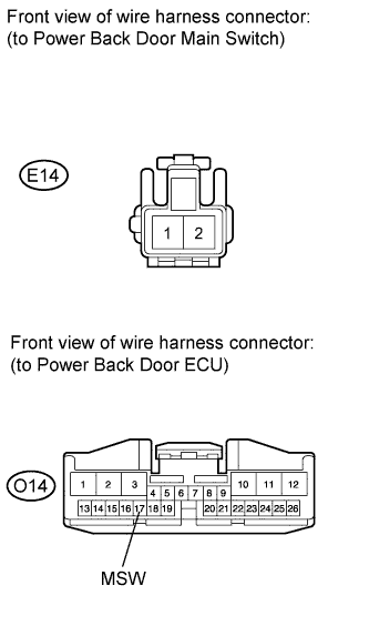
Disconnect the O14 ECU connector.
Measure the resistance according to the value(s) in the table below.
- Standard resistance:
Tester Connection
Condition
Specified Condition
E14-1 (UL) - O14-17 (MSW)
Always
Below 1 Ω
E14-2 (E) - Body ground
Always
Below 1 Ω
E14-1 (UL) - Body ground
Always
10 kΩ or higher
|
|
||||
| OK | ||
|
||
| ||