 |
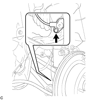
Remove the bolt and separate the rear speed sensor from the rear axle carrier sub-assembly.
- NOTICE:
- Keep the sensor tip and rear speed sensor installation hole free from foreign matter.
REAR AXLE HUB (for 4WD) > REMOVAL |
| 1. REMOVE REAR WHEEL |
| 2. SEPARATE REAR SPEED SENSOR |
|
Remove the bolt and separate the rear speed sensor from the rear axle carrier sub-assembly.
| 3. REMOVE REAR AXLE SHAFT NUT |
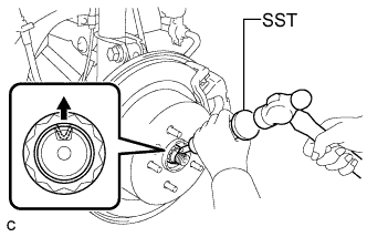 |
Using SST and a hammer, release the staked part of the rear axle shaft nut.
While applying the brakes, remove the rear axle shaft nut.
| 4. SEPARATE REAR DISC BRAKE CALIPER ASSEMBLY |
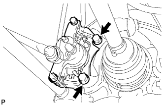 |
Remove the 2 bolts and separate the rear disc brake caliper assembly.
| 5. REMOVE REAR DISC |
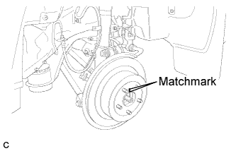 |
Put matchmarks on the rear disc and the axle hub.
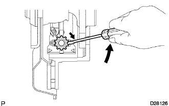 |
Release the parking brake and remove the rear disc.
| 6. REMOVE REAR AXLE HUB AND BEARING ASSEMBLY |
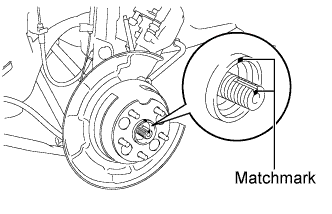 |
Put matchmarks on the drive shaft and axle hub.
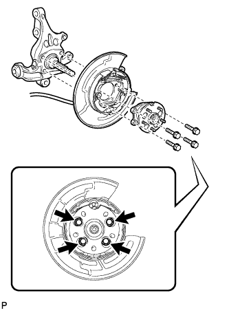 |
Remove the 4 bolts and the rear axle hub and bearing assembly.
| 7. SEPARATE NO. 3 PARKING BRAKE CABLE ASSEMBLY |
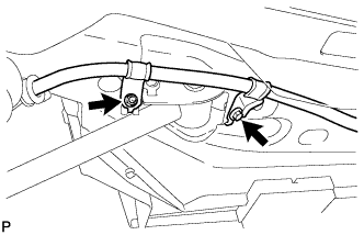 |
Remove the bolt and the nut, and separate the No. 3 parking brake cable assembly.
| 8. REMOVE REAR STRUT ROD ASSEMBLY |
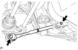 |
Remove the 2 bolts, the 2 nuts, and the rear strut rod assembly.
| 9. REMOVE REAR AXLE CARRIER SUB-ASSEMBLY |
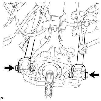 |
Loosen the 2 bolts.
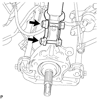 |
Remove the 2 bolts and 2 nuts, and separate the rear shock absorber with coil spring (lower side) from the rear axle carrier sub-assembly.
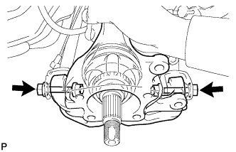 |
Remove the 2 bolts, the 2 nuts, and the rear axle carrier sub-assembly.