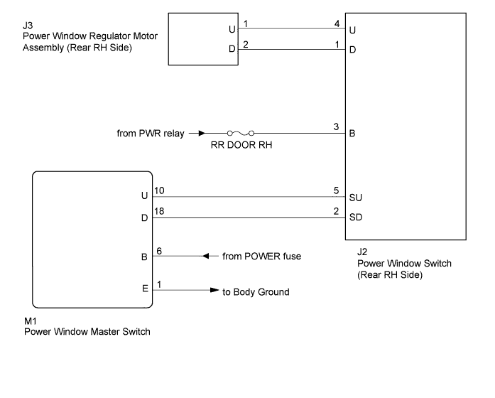
POWER WINDOW CONTROL SYSTEM > Rear Power Window RH does not Operate with Rear Power Window Switch RH |
| 1.CHECK POWER WINDOW SWITCH (REAR RH) (POWER SOURCE) |
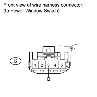 |
Disconnect the J2 connector.
Measure the voltage according to the value(s) in the table below.
| Tester Connection | Condition | Specified Condition |
| J2-3 (B) - Body ground | Ignition switch on (IG) | 11 to 14 V |
|
| ||||
| OK | |
 |
| 2.INSPECT POWER WINDOW SWITCH (REAR RH) |
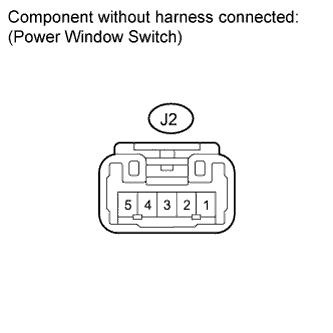 |
Measure the resistance when the switch is operated according to the value(s) in the table below.
| Tester Connection | Switch Condition | Specified Condition |
| 1 (D) - 2 (SD) | UP | Below 1 Ω |
| 3 (B) - 4 (U) | Below 1 Ω | |
| 1 (D) - 2 (SD) | OFF | Below 1 Ω |
| 4 (U) - 5 (SU) | Below 1 Ω | |
| 4 (U) - 5 (SU) | DOWN | Below 1 Ω |
| 1 (D) - 3 (B) | Below 1 Ω |
|
| ||||
| OK | |
|
| 3.CHECK HARNESS AND CONNECTOR (SWITCH (REAR RH) - MOTOR (REAR RH)) |
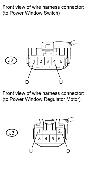 |
Disconnect the J2 and J3 connectors.
Measure the resistance according to the value(s) in the table below.
| Tester Connection | Condition | Specified Condition |
| J2-4 (U) - J3-1 (U) | Always | Below 1 Ω |
| J2-1 (D) - J3-2 (D) | Always | Below 1 Ω |
| J2-4 (U) - Body ground | Always | 10 kΩ or higher |
| J2-1 (D) - Body ground | Always | 10 kΩ or higher |
|
| ||||
| OK | |
|
| 4.INSPECT POWER WINDOW REGULATOR MOTOR ASSEMBLY (REAR RH) |
Check power window regulator motor operation.
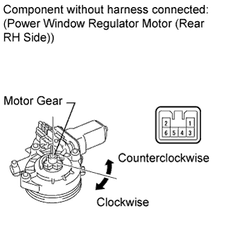 |
Remove the power window regulator motor (Click here).
Apply battery voltage to the motor connector according to the table below.
| Measurement Condition | Specified Condition |
| Battery negative (-) → Terminal 1 Battery positive (+) → Terminal 2 | Motor gear rotates clockwise |
| Battery negative (-) → Terminal 2 Battery positive (+) → Terminal 1 | Motor gear rotates counterclockwise |
Check PTC operation:
Install the power window regulator motor (Click here).
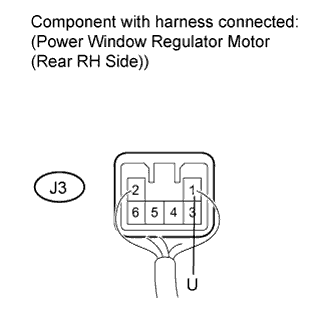 |
Connect an electrical tester DC 400 A probe to the wire harness of terminal 1.
Fully close the door glass by pressing the power window UP switch. Wait for approximately 60 seconds.
Continue to press the power window UP switch and measure how long it takes for the electrical current to change from a range of 16 to 28 A to approximately 1 A (Inspection of current shut-off).
60 seconds after the previous step, press the power window DOWN switch (rear RH side).
|
| ||||
| OK | |
|
| 5.CHECK HARNESS AND CONNECTOR (MASTER SWITCH - SWITCH (REAR RH)) |
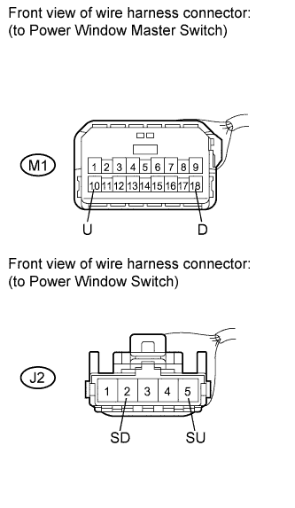 |
Disconnect the M1 and J2 connector.
Measure the resistance according to the value(s) in the table below.
| Tester Connection | Condition | Specified Condition |
| M1-10 (U) - J2-5 (SU) | Always | Below 1 Ω |
| M1-18 (D) - J2-2 (SD) | Always | Below 1 Ω |
| M1-10 (U) - Body ground | Always | 10 kΩ or higher |
| M1-18 (D) - Body ground | Always | 10 kΩ or higher |
|
| ||||
| OK | ||
 | ||
| ||
