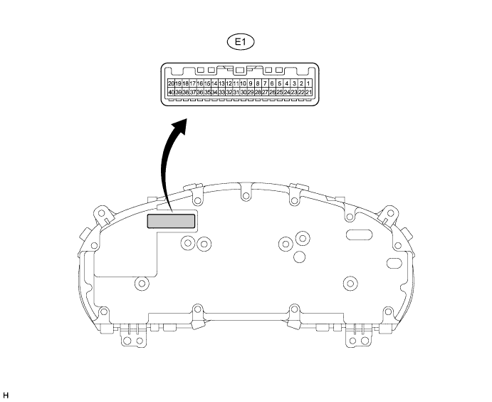
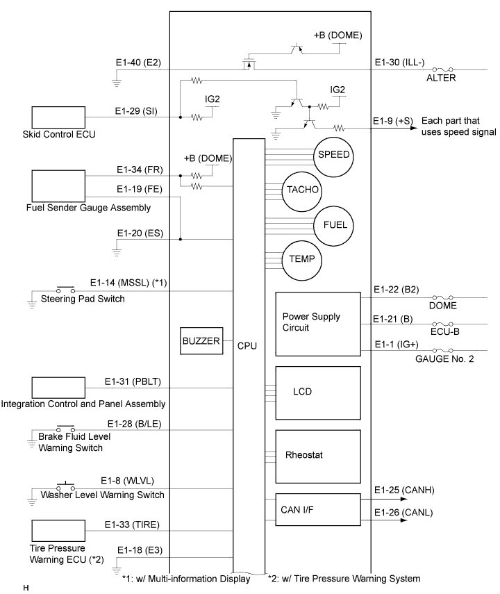
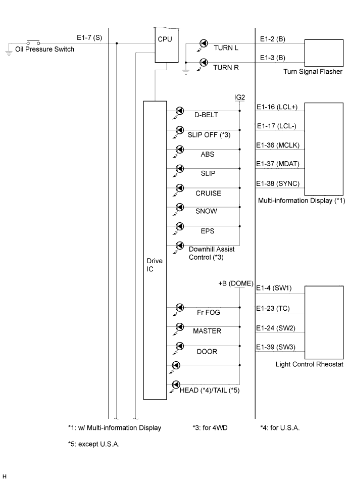
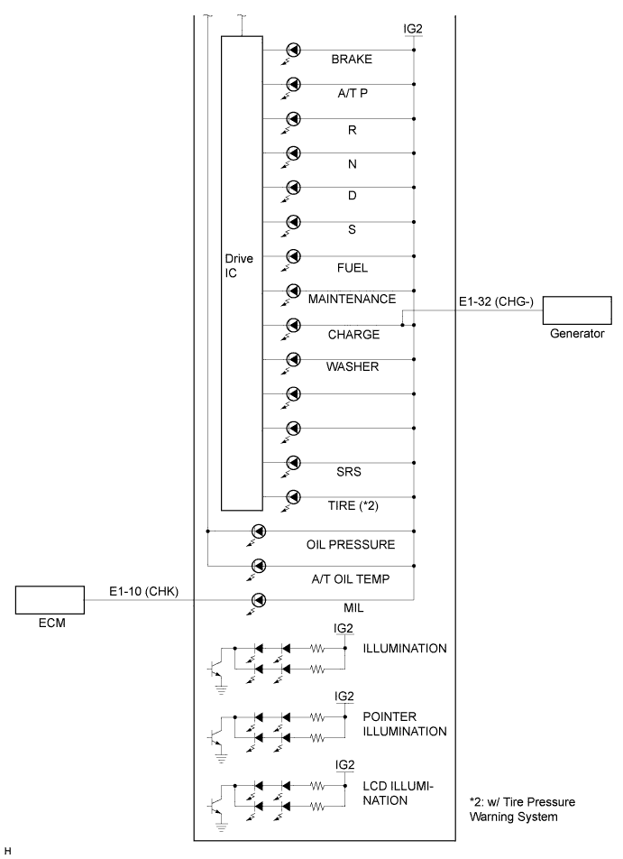
Terminal No. (Symbol)
| Wiring Color
| Terminal Description
| Condition
| Specified Condition
|
E1-1 (IG+) - Body ground
| O - Body ground
| Ignition switch signal
| Ignition switch off
| Below 1 V
|
Ignition switch on (IG)
| 11 to 14 V
|
E1-2 (B) - Body ground
| G - Body ground
| Turn indicator light signal
| Ignition switch on (IG), turn signal LH indicator light OFF
| Below 1 V
|
Ignition switch on (IG), turn signal LH indicator light ON
| 11 to 14 V
|
E1-3 (B) - Body ground
| GR - Body ground
| Turn indicator light signal
| Ignition switch on (IG), turn signal RH indicator light OFF
| Below 1 V
|
Ignition switch on (IG), turn signal RH indicator light ON
| 11 to 14 V
|
E1-4 (SW1) - Body ground
| B - Body ground
| Light control rheostat signal (Tail cancel switch)
| Ignition switch on (IG), turn the light control rheostat knob fully downwards (Tail cancel off)
| Below 1 V
|
Ignition switch on (IG), turn the light control knob rheostat fully upwards (Tail cancel on)
| 4 to 6 V
|
E1-7 (S) - Body ground
| Y - Body ground
| Oil pressure warning light signal
| Ignition switch on (IG), oil pressure warning light OFF
| 11 to 14 V
|
Ignition switch on (IG), oil pressure warning light ON
| Below 1.5 V
|
E1-8 (WLVL) - Body ground
| P - Body ground
| Washer level warning light signal
| Ignition switch on (IG), WASHER warning light OFF
| 11 to 14 V
|
Ignition switch on (IG), WASHER warning light ON
| Below 1.5 V
|
E1-9 (+S) - Body ground
| LG - Body ground
| Speed signal for other system (Output)
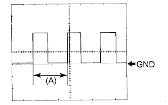
| Turn the wheel slowly
| Pulse generation
(See waveform)
|
E1-10 (CHK) - Body ground
| W - Body ground
| MIL (Check engine warning light) signal
| Ignition switch on (IG), MIL ON
| Below 1 V
|
Ignition switch on (IG), MIL OFF
| 11 to 14 V
|
E1-14 (MSSL) (*1) - Body ground
| P - Body ground
| Steering pad switch signal
| Ignition switch on (IG), DISP switch OFF
| 4 to 6 V
|
Ignition switch on (IG), DISP switch ON
| Below 1 V
|
E1-16 (LCL+) (*1) - Body ground
| SB - Body ground
| Multi-information display signal
| Ignition switch off
| Below 1 V
|
Ignition switch on (IG)
| 11 to 14 V
|
E1-17 (LCL-) (*1) - Body ground
| G - Body ground
| Multi-information display signal
| Ignition switch off
| Below 1 V
|
Ignition switch on (IG)
| 11 to 14 V
|
E1-18 (E3) - Body Ground
| W-B - Body ground
| Ground
| Always
| Below 1 V
|
E1-19 (FE) - Body ground
| W-B - Body ground
| Ground (Fuel ground)
| Always
| Below 1 V
|
E1-20 (ES) - Body ground
| R - Body ground
| Ground (Signal ground)
| Always
| Below 1 V
|
E1-21 (B) - Body ground
| SB - Body ground
| Battery
| Always
| 11 to 14 V
|
E1-22 (B2) - Body ground
| BR - Body ground
| Battery
| Always
| 11 to 14 V
|
E1-23 (TC) - Body ground
| R - Body ground
| Light control rheostat signal (Tail cancel switch)
| Ignition switch on (IG), turn the light control rheostat knob fully downwards
| 4 to 6 V
|
Ignition switch on (IG), turn the light control rheostat knob fully upwards
| Below 1 V
|
E1-24 (SW2) - Body ground
| BR - Body ground
| Light control rheostat signal
| Ignition switch on (IG), rheostat knob position is on MIN.
| Below 1 V
|
Ignition switch on (IG), rheostat knob position is on MAX.
| 4 to 6 V
|
E1-25 (CANH) - Body ground
| P - Body ground
| CAN communication line
| Ignition switch off
| 200 Ω or higher
|
E1-26 (CANL) - Body ground
| W - Body ground
| CAN communication line
| Ignition switch off
| 200 Ω or higher
|
E1-28 (B/LE) - Body ground
| SB - Body ground
| Brake fluid level warning light signal
| Ignition switch on (IG), BRAKE warning light OFF
| 11 to 14 V
|
Ignition switch on (IG), BRAKE warning light ON
| Below 1.5 V
|
E1-29 (SI) - Body ground
| BR - Body ground
| Speed signal for other system (Input)
| Ignition switch on (IG), turn the wheel slowly.
| Pulse generation
(See waveform)
|
E1-30 (ILL-) - Body ground
| R - Body ground
| Illumination signal
| Ignition switch on (IG), light control switch is in the HEAD/TAIL position.
| 11 to 14 V
|
E1-31 (PBLT) - Body ground
| BR - Body ground
| Passenger seat belt warning light signal
| Sit on the passenger seat, ignition switch on (IG), passenger seat belt warning light OFF
| 11 to 14 V
|
Sit on the passenger seat, ignition switch on (IG), front passenger side seat belt warning light is blinking.
| Below 1 V
|
E1-32 (CHG-) - Body ground
| V - Body ground
| Charge warning light signal
| Ignition switch on (IG), charge warning light ON
| Below 1.5 V
|
Ignition switch on (IG), charge warning light OFF
| 11 to 14 V
|
E1-33 (TIRE) (*2) - Body ground
| Y - Body ground
| Tire pressure warning signal
| Ignition switch on (IG), tire pressure warning light ON
| 8 to 15 V
|
Ignition switch on (IG), tire pressure warning light OFF
| Below 1.5 V
|
E1-34 (FR) - Body ground
| GR - Body ground
| Fuel signal
| Ignition switch on (IG), fuel level is FULL.
| Below 2 V
|
Ignition switch on (IG), fuel level is EMPTY.
| 4 to 7 V
|
E1-36 (MCLK) (*1) - Body ground
| R - Body ground
| Multi-information display signal
| Ignition switch on (IG)
| Pulse generation
|
E1-37 (MDAT) (*1) - Body ground
| Y - Body ground
| Multi-information display signal
| Ignition switch on (IG)
| Pulse generation
|
E1-38 (SYNC) (*1) - Body ground
| L - Body ground
| Multi-information display signal
| Ignition switch on (IG)
| Pulse generation
|
E1-39 (SW3) - Body ground
| P - Body ground
| Light control rheostat signal
| Ignition switch on (IG), rheostat knob position is on MIN.
| Below 1 V
|
Ignition switch on (IG), rheostat knob position is on MAX.
| 4 to 6 V
|
E1-40 (E2) - Body ground
| W - Body ground
| Ground (Power ground)
| Always
| Below 1 V
|