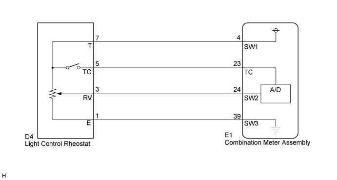
METER / GAUGE SYSTEM > Operating Light Control Rheostat does not Change Light Brightness |
| 1.SYSTEM CHECK |
Ignition switch on (IG).
Turn the light control rheostat knob fully upwards.
Turn the light control rheostat knob fully downwards.
Turn the light control rheostat knob fully upwards and light control switch is on Tail or HEAD.
Check the meter illumination.
| Result | Proceed to |
| Meter illumination does not change when operating the light control rheostat knob. | A |
| Dimmer cancel does not operate (Meter illumination does not dim). | B |
|
| ||||
| A | |
 |
| 2.READ VALUE USING TECHSTREAM (RHEOSTAT) |
Connect Techstream to the DLC3.
Ignition switch on (IG).
Turn the tester on.
Enter the following menus: Body Electrical / Combination Meter / Active Test.
Check the values by referring to the table below.
| Tester Display | Measurement Item/Range | Normal Condition | Diagnostic Note |
| Rheostat value | Light control rheostat/Min.: 0%, Max.: 100% | Light control rheostat switch is Dark (0%) → Bright (100%) | - |
|
| ||||
| OK | |
|
| 3.READ VALUE USING TECHSTREAM (TAIL CANCEL SW) |
Connect Techstream to the DLC3.
Ignition switch on (IG).
Turn the tester on.
Enter the following menus: Body Electrical / Combination Meter / Data List.
Check the values by referring to the table below.
| Tester Display | Measurement Item/Range | Normal Condition | Diagnostic Note |
| Tail Cancel SW | Tail cancel switch is OFF/ON | OFF: Light control rheostat position is except below | - |
| ON: Turn the Light control rheostat knob fully upwards | - |
|
| ||||
| OK | ||
 | ||
| ||
| 4.CHECK HARNESS AND CONNECTOR (COMBINATION METER - LIGHT CONTROL RHEOSTAT) |
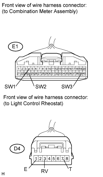 |
Disconnect the E1 and D4 connectors.
Measure the resistance according to the value(s) in the table below.
| Tester Connection | Condition | Specified Condition |
| E1-4 (SW1) - D4-7 (T) | Always | Below 1 Ω |
| E1-24 (SW2) - D4-3 (RV) | Always | Below 1 Ω |
| E1-39 (SW3) - D4-1 (E) | Always | Below 1 Ω |
| D4-1 (E) - Body ground | Always | 10 kΩ or higher |
| D4-3 (RV) - Body ground | Always | 10 kΩ or higher |
| D4-7 (T) - Body ground | Always | 10 kΩ or higher |
|
| ||||
| OK | |
|
| 5.INSPECT LIGHT CONTROL RHEOSTAT |
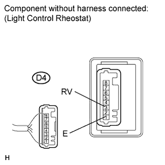 |
Remove the light control rheostat with the connector still connected.
Measure the resistance according to the value(s) in the table below.
| Tester Connection | Condition | Specified Condition |
| D4-1 (E) - D4-3 (RV) | Turn the light control rheostat knob fully upwards | 8 kΩ or higher |
| D4-1 (E) - D4-3 (RV) | Rheostat knob position is between MIN. and MAX. | The value changes gradually (Between below 1 to 8 kΩ) |
| D4-1 (E) - D4-3 (RV) | Turn the light control rheostat knob fully downwards | Below 1 Ω |
|
| ||||
| OK | ||
| ||
| ||
| 6.CHECK HARNESS AND CONNECTOR (COMBINATION METER - LIGHT CONTROL RHEOSTAT) |
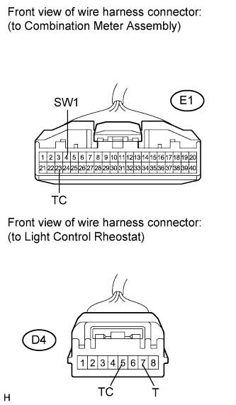 |
Disconnect the E1 and D4 connectors.
Measure the resistance according to the value(s) in the table below.
| Tester Connection | Condition | Specified Condition |
| D4-5 (TC) - E1-23 (TC) | Always | Below 1 Ω |
| D4-7 (T) - E1-4 (SW1) | Always | Below 1 Ω |
| D4-5 (TC) - Body ground | Always | 10 kΩ or higher |
| D4-7 (T) - Body ground | Always | 10 kΩ or higher |
|
| ||||
| OK | |
|
| 7.INSPECT LIGHT CONTROL RHEOSTAT |
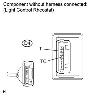 |
Remove the light control rheostat with connector still connected.
Measure the resistance according to the value(s) in the table below.
| Tester Connection | Condition | Specified Condition |
| D4-5 (TC) - D4-7 (T) | Turn the light control rheostat knob fully downwards | Below 1 Ω |
| D4-5 (TC) - D4-7 (T) | Turn the light control rheostat knob fully upwards (Tail cancel ON) | 8 kΩ or higher |
|
| ||||
| OK | ||
| ||
| ||

